A difference between measured 200 mm I-beam weight per meter and a published table should first trigger a comparison of section identity, weighing conditions, and actual length. Accepting or rejecting the beam from the percentage difference alone risks using the wrong reference. A nominal depth of 200 mm does not specify flange width, web thickness, flange thickness, or manufacturing route, all of which affect mass.
Start with the complete section designation on the order and its matching dimensional table. Then calculate measured mass per meter from net beam mass and measured length. Once those two values share the same basis, the remaining difference can be assessed against the applicable dimensional and mass tolerances.
The table must describe the section actually delivered
Several beam families can share a nominal 200 mm depth while having different cross-sectional areas. Narrow-flange, wide-flange, parallel-flange, and tapered-flange sections are not interchangeable references. Even within one section family, different weight series can use similar depths with different flange and web dimensions.
A search result headed “200mm i beam weight per meter” often omits the designation needed to identify a specific section. An abbreviated invoice description creates the same problem. Match the table entry to the full ordered designation, including the section series, dimensional standard, and any suffix identifying a particular size or weight variant.
Also establish whether the delivered beam is hot rolled or fabricated from welded plates. A welded I-section with a nominal depth of 200 mm follows its specified plate dimensions and fabrication details. Its mass should not automatically be compared with a rolled-section table, even when the external outline looks similar.
A document carrying the correct steel grade does not settle section identity. Grade describes material requirements; the section designation describes geometry. Traceability must connect both to the physical pieces being measured.
Establish a reliable measured value
The basic calculation is straightforward:
Measured mass per meter = net beam mass in kilograms ÷ actual beam length in meters.
The difficult part is establishing the inputs. Net mass excludes packaging, straps, timber supports, lifting accessories, and other items included in the scale reading. Record gross mass and tare separately so that the calculation can be reconstructed. A reused tare value becomes unreliable when packaging changes between bundles.
Use measured length rather than the nominal ordered length. Dividing by a nominal length that exceeds the actual length makes the calculated mass per meter appear too low. The reverse makes it appear too high. Square cuts, angled ends, and irregular end conditions need a consistent length convention that matches the applicable inspection method.
For a bundle containing different lengths, divide its net mass by the sum of the actual member lengths. Multiplying the piece count by one nominal length introduces an avoidable error. A bundle result also averages the contents: one heavier section can conceal a lighter piece, so a satisfactory average does not establish that every member conforms.
Scale resolution and calibration matter most when the suspected discrepancy is small. Confirm that the weighing equipment is suitable for the load and that the entire load is supported by the weighing system. Contact with the floor, a rack, or another bundle can divert force away from the scale. During suspended weighing, swinging or partly supported loads produce unstable readings.
Repeat a questionable measurement after repositioning the load and confirming tare. Stable repeat readings support the weighing result, although they do not prove that the scale has no systematic error. Where uncertainty could change the acceptance decision, use an independent verified weighing method.
Locate the dimensional source of the difference
Theoretical mass follows cross-sectional area multiplied by the assumed steel density. For ordinary structural steel calculations, a commonly used density is 7,850 kg/m³. With area expressed in square millimeters, the corresponding relationship is:
Theoretical mass in kg/m = cross-sectional area in mm² × 0.00785.
Use the density basis stated by the relevant table when available. Table values are calculated references, so their displayed precision and rounding should also be considered when interpreting a very small difference.
For a simplified parallel-flange I-section, ignoring root radii and edge details, area can be estimated as 2btf + (h − 2tf)tw, where b is flange width, h is overall depth, tf is flange thickness, and tw is web thickness. This estimate helps identify which dimensions drive a discrepancy. It is not an exact reconstruction of a rolled profile.
Root fillets add area where the web meets the flanges. Tapered flanges require their actual geometry rather than a single rectangular thickness assumption. Welded sections introduce weld metal and fabrication details that also affect the finished mass. Ignoring these features can make a dimensional estimate disagree with a correct table.
Measure thickness at the locations specified by the applicable inspection method. A reading taken close to a root radius can include the transition into the flange and overstate web thickness. On a tapered flange, thickness changes across the width, so readings from different positions are not directly comparable.
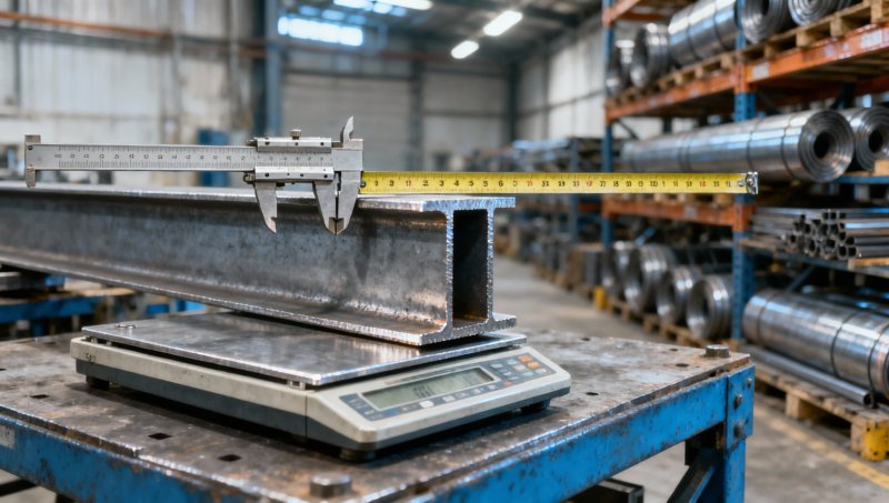
Take readings at several positions along representative members, away from distorted cut ends and isolated surface defects. Record flange width, overall depth, web thickness, and flange thickness together. A depth close to 200 mm cannot compensate for a web or flange that is thinner than specified.
Dimensional evidence also helps distinguish two superficially similar outcomes. A consistently lighter beam with consistently smaller thickness measurements points toward reduced section area. A lighter calculated result with dimensions matching the intended section directs attention back to length, tare, scale performance, or processing losses.
Separate coating and processing effects from steel mass
Published section tables generally describe the theoretical steel section without subsequently applied coatings. Paint or galvanizing adds mass, so a finished beam can weigh more per meter than its uncoated reference while its steel dimensions remain correct. Uneven coating buildup, drips, and retained material introduce further variation.
Where coating mass materially affects the comparison, use documented coating information or a validated measurement method. A rough deduction based on nominal coating thickness and estimated surface area can support an investigation, but it should not become the acceptance basis without accounting for its uncertainty. Thick coatings can also inflate external thickness readings.
Mixed deliveries require separate references for separate profiles. Painted or galvanized framing components such as C-Shaped Steel have their own section geometry and coating condition; including them in an I-beam bundle weight makes the calculated I-beam mass per meter invalid.
Drilled holes, flange copes, slots, and end cuts remove steel. Comparing a processed member directly with an uninterrupted-section table therefore produces an expected downward difference. Reconcile those features against the fabrication drawing before attributing the shortfall to rolling tolerances. Attached plates, stiffeners, welds, and connection hardware produce the opposite effect.
Water, mud, and retained debris increase a weighing result without representing useful section area. Heavy corrosion creates a different problem: corrosion products and trapped moisture complicate gross mass, while metal loss reduces the remaining section. A weathered member needs assessment of its remaining geometry rather than a simple comparison with original nominal mass.
Apply the tolerance that governs the order
After matching the reference and resolving measurement effects, calculate the deviation:
Deviation (%) = [(measured mass per meter − reference mass per meter) ÷ reference mass per meter] × 100.
The sign matters: a negative result indicates a lower measured mass, and a positive result indicates a higher one. The percentage alone does not establish acceptance. There is no universal tolerance that applies to every beam described as 200 mm deep.
Read the tolerance provisions incorporated into the order, including any supplementary requirements. Establish whether a mass limit applies to an individual piece, a group of pieces, or a delivery lot. These are different acceptance bases. A bundle average cannot be substituted for an individual-member requirement.
Mass tolerance and dimensional tolerance must also be assessed separately where both apply. Acceptable total mass can coexist with an undersized web and oversized flanges. Extra steel in one location does not necessarily offset missing steel elsewhere for structural behavior.
If the specification provides dimensional tolerances but no applicable mass acceptance limit, do not create an arbitrary percentage from an unrelated table. Resolve the contractual basis before releasing disputed material. Measurement uncertainty should remain visible, especially when the result lies close enough to a boundary that a plausible weighing or length error would change the decision.
Use the discrepancy pattern to decide what happens next
A consistent offset across correctly identified pieces suggests a shared cause, such as the wrong table entry, a common dimensional shift, coating mass, or systematic weighing error. Large variation between pieces suggests mixed sections, inconsistent processing, variable dimensions, or unreliable measurements. Group the results by designation and processing condition before interpreting the pattern.
Unresolved identity or dimensional discrepancies justify holding the affected material from installation. Extend the investigation when initial sampling reveals mixed markings, inconsistent geometry, or unexplained variation. Increasing the sample without correcting a faulty weighing method simply produces more unreliable data.
Weight per meter is useful evidence of section quantity, but it cannot establish load capacity by itself. Flange geometry strongly affects bending behavior; web dimensions influence shear behavior and local stability. Grade, straightness, restraint, connections, and loading conditions remain relevant to structural suitability. A heavier beam is not automatically an acceptable substitute for the specified section.
The discrepancy record should retain piece or bundle identification, the ordered designation, table source, gross and tare readings, measured lengths, dimensional results, coating and processing condition, and the tolerance provision used. Include measurement locations and photographs where they clarify the evidence. Record the basis for acceptance, rejection, or engineering disposition so that the decision remains traceable to the actual material.
Please give us a message


Please enter what you want to find