Why a 200 mm I-beam's weight alone cannot establish load capacity
A 200 mm I-beam may appear suitable based on its weight per metre, but mass alone cannot establish its load capacity. A search for “200mm i beam weight” is only the starting point: section geometry, steel grade, span, support conditions, load distribution, and lateral restraint all influence structural performance. Beams with similar weights can have different bending resistance, deflection, and buckling behaviour.
The practical problem often starts with a quotation. One supplier offers a “200 mm beam,” another offers a section with roughly the same mass, and both look interchangeable on a purchasing spreadsheet. They may not be. Before comparing prices or approving a substitution, establish exactly which section is being offered and how it will work in the structure.
“200 mm” identifies a depth, not a complete section
In common beam descriptions, 200 mm usually refers to nominal overall depth. It does not specify flange width, web thickness, flange thickness, root radii, or whether the section has parallel or tapered flanges. Depending on the section series, nominal depth may also differ from the tabulated actual dimension.
A European IPE section, a broader-flange section, and a beam supplied to a JIS or GB section designation should not be treated as equivalent merely because their nominal depths are similar. A welded I-section introduces another distinction: its plate arrangement, weld details, and fabrication tolerances need examination alongside its dimensions.
This is why there is no single reliable weight figure for every 200 mm I-beam. A useful section table must identify the designation and dimensional standard. Without those, a kg/m value is an incomplete description, not a structural specification.
For preliminary checking, mass per metre follows the relationship m = ρA, where ρ is material density and A is cross-sectional area in compatible units. That calculation tells you how much steel is present. It does not tell you where the steel is located.
Where the steel sits matters more than the scale reading
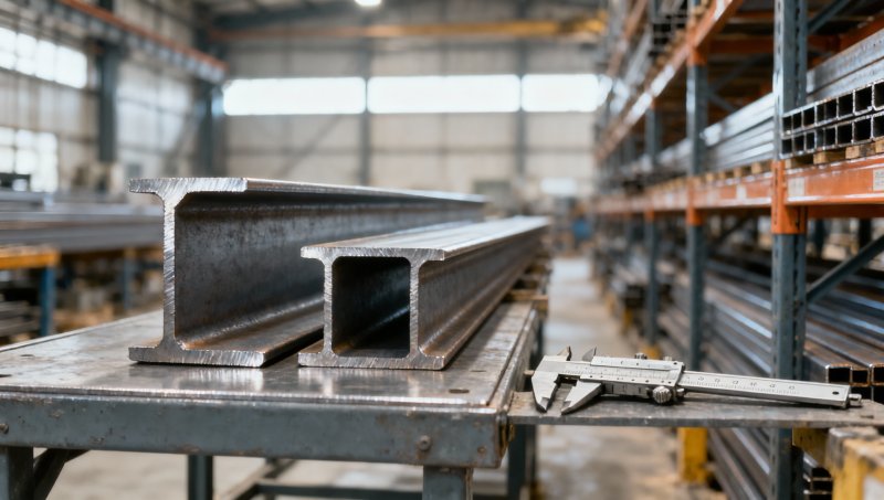
Under major-axis bending, material farther from the neutral axis makes a larger contribution to the second moment of area, I. This is the reason an I-section puts substantial material into its flanges rather than distributing it uniformly through a solid rectangular section.
Two sections can therefore have similar area and mass but different bending stiffness. A wider flange or a different flange-to-web thickness balance can also change minor-axis stiffness, torsional properties, and susceptibility to instability. More weight is not automatically more useful resistance for the governing failure mode.
For evaluation, look beyond area to the major-axis second moment of area and section modulus. The elastic section modulus, W, connects bending moment to elastic bending stress through σ = M/W. Plastic section modulus may support a plastic resistance calculation, but only where section classification, stability, and the applicable design rules permit it.
Be careful with axis labels. Tables may identify the strong axis as x-x or y-y, depending on the convention. Also verify units: cm⁴ and mm⁴ are not interchangeable, and neither are cm³ and mm³. A copied spreadsheet with an unnoticed unit conversion error can produce a convincing but incorrect result.
Span and loading can overturn an apparently sensible selection
Consider a simply supported beam carrying a uniformly distributed load. Under the idealised elastic model, its maximum bending moment is M = wL²/8, and maximum deflection is δ = 5wL⁴/(384EI). Here, w is load per unit length, L is span, and E is elastic modulus. These equations assume the stated support and loading conditions; they are not universal capacity formulas.
Their implications are useful. Doubling the span while keeping the same section and distributed load increases the bending moment fourfold and deflection sixteenfold. The beam’s weight per metre has not changed at all.
Load position matters too. For a central point load on the same simply supported beam, maximum moment is M = PL/4. A uniformly distributed load with the same total force produces half that maximum moment. A machine foot, suspended service, or storage rack reaction cannot simply be averaged along the beam without checking the consequences.
Support assumptions deserve equal scrutiny. A beam resting on seats is not automatically fixed-ended because someone has added bolts. Genuine rotational restraint depends on connection stiffness and the supporting structure. Continuity may reduce some span moments, but it introduces support moments and different restraint demands.
There is also a distinction between carrying a load without failure and performing acceptably in service. Deflection, vibration, cladding compatibility, and equipment alignment can control selection before strength is exhausted. The allowable deflection must come from the project requirements and governing rules, not a span ratio chosen simply because it is familiar.
Higher strength does not cure every problem
Steel grade affects yield-based resistance. However, changing to a higher-strength structural grade generally does not provide a comparable increase in elastic modulus. If the beam is governed by elastic deflection, a grade upgrade alone may leave the problem essentially unchanged.
Yield strength also needs to be read against the applicable material specification and thickness range. A grade name without its standard, delivery condition, and inspection documentation is insufficient for final verification.
Material data must remain attached to the correct product. For example, 201 Stainless Steel Coil may be considered for formed covers or decorative components in an industrial assembly. It is a separate material choice, not evidence for the strength of a carbon-steel support beam. Stainless coil properties, surface finishes, and corrosion suitability should be evaluated independently; they cannot be transferred into the beam calculation.
The design framework matters as well. AISC 360 and EN 1993 provide structural steel design provisions, but their resistance formats and detailed rules should not be mixed casually. ASTM material specifications, dimensional standards, and a structural design code serve different purposes. Meeting a product specification does not, by itself, demonstrate that the installed beam meets the project’s design requirements.
The overlooked limit is often restraint or a local detail
A beam may reach its lateral-torsional buckling limit before reaching its cross-sectional bending resistance. This becomes particularly relevant when the compression flange lacks effective lateral restraint. Unbraced length, moment distribution, load application height, torsional properties, and end restraint all influence the assessment.
Do not count every contact point as a brace. Decking, purlins, or attached panels provide restraint only if their connections and load paths can deliver the required strength and stiffness. The construction stage needs its own consideration: a beam that will eventually be restrained by completed flooring may be unrestrained during erection.
Local buckling is a different issue. Slender flange outstands or webs may limit the usable section resistance. Adding depth with relatively thin plates can look efficient by weight while creating a less favourable local stability check.
Then there are concentrated reactions. A beam supporting equipment or framing into a short bearing seat may require checks for web bearing, web crippling, or other local effects under the governing code. Stiffeners may be needed even when the overall bending calculation looks comfortable. Holes, notches, corrosion loss, and connection details can further change what the delivered section can safely do.
What to request before approving a supplier’s beam
For an initial comparison, a concise technical submission is more useful than an unsupported “load capacity” claim. Ask for:
- The full section designation, dimensional standard, actual dimensions, and nominal mass per metre.
- Section properties, including strong- and weak-axis second moments of area, section moduli, and properties needed for stability calculations.
- The material standard, grade, applicable thickness-dependent properties, and traceable mill documentation.
- Manufacturing route and relevant tolerances, with weld and inspection information for fabricated sections.
- The assumptions behind any proposed capacity: span, loading pattern, supports, restraint, design code, and serviceability criteria.
Measured weight remains useful. It supports transport planning, quantity reconciliation, and an initial dimensional consistency check. But a weight discrepancy should be investigated against dimensions, measurement conditions, and permitted tolerances; it should not be converted directly into a percentage change in load capacity.
For a Chinese manufacturer and exporter such as Hongteng Fengda, supplying both standard sections and customised structural components, the technical handover should connect the offered product to the project specification. Cross-border substitutions need particular care: the nearest available section is not necessarily an equivalent section, and a similar grade label does not establish compliance with another standard.
A workable approval sequence is to confirm section identity, verify material properties, calculate load effects, check strength and stability, then assess serviceability and connections. If one of those inputs is missing, approval should remain conditional.
The useful answer to “How much can this 200 mm I-beam carry?” is therefore tied to a defined installation, not a weight table. Use kg/m to identify and compare the product. Use verified section properties and a project-specific structural calculation to establish whether it can carry the required load.
Please give us a message


Please enter what you want to find