Elongated bolt holes usually indicate connection movement and local steel deformation. For maintenance teams, the immediate priority is identifying why movement occurred before tightening fasteners.
When inspecting an angulo con perforaciones, consider loose bolts, excessive clearance, repeated loading, misalignment, and inadequate connection geometry. Several causes often act together.
Some holes are intentionally slotted during manufacture, so shape alone does not prove damage. Compare the connection with drawings, original dimensions, and adjacent undamaged holes.
This guide explains how to recognize likely causes, collect useful inspection evidence, and select corrective actions that address recurring damage rather than its appearance.
Is the hole intentionally slotted, or has the steel deformed?
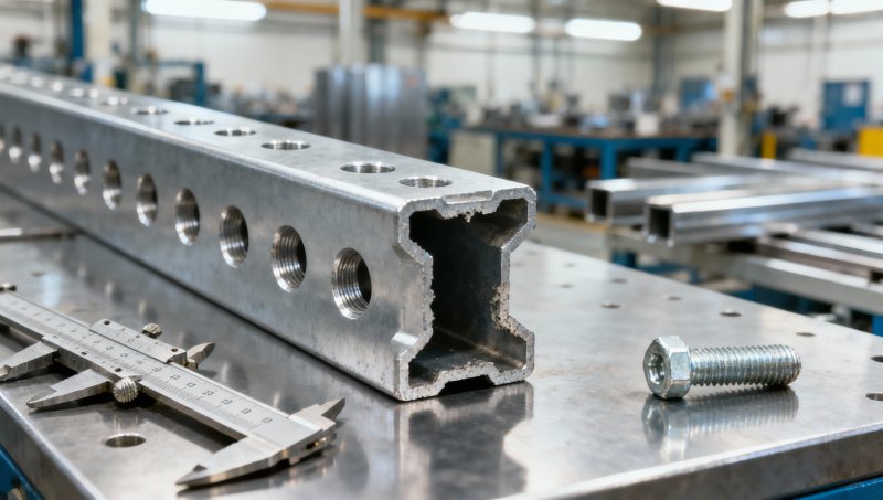
Start by confirming the specified hole shape and dimensions. Perforated angles may contain round holes, short slots, or long slots intended for particular assembly requirements.
A manufactured slot generally has consistent dimensions, regular edges, and matching geometry elsewhere. Service damage may show displaced metal, asymmetric widening, polished surfaces, or cracked coatings.
However, appearance is only preliminary evidence. Punching can leave burrs, and coatings can obscure deformation, so compare measurements against the approved fabrication drawing and tolerances.
Measure the hole along its longest axis and perpendicular to it, recording both dimensions. Also record angle thickness, hole pitch, and distance to the nearest edge.
If access requires bolt removal, first establish how the connection will remain supported. Removing a fastener from a loaded assembly can redistribute forces unexpectedly.
The direction of elongation often indicates relative movement between connected parts. It does not, by itself, establish the complete loading history or root cause.
Look for matching damage on the mating component, bolt shank, and washers. A sound diagnosis considers the entire connection rather than one visibly enlarged hole.
Distinguish hole elongation from member elongation and material elongation values. A steel grade’s tensile-test elongation percentage does not describe acceptable deformation around a bolt.
Which operating conditions most often cause elongated bolt holes?
The direct mechanism is usually concentrated contact between the bolt shank and hole wall. If local bearing stresses become excessive, the steel can deform permanently.
Movement can begin because the assembly slips, fits poorly, experiences unexpected loads, or loses section thickness. Identifying that initiating condition determines the appropriate repair.
Loose fasteners and repeated connection movement
Loose fasteners can allow connected parts to move before the bolt contacts the hole wall. Repeated contact may combine plastic deformation with surface wear.
Possible contributors include vibration, incomplete installation, coating compression, joint settlement, or unsuitable locking arrangements. A loose nut observed today may also result from earlier deformation.
Do not assume every structural connection relies on friction. Bearing-type connections transfer shear through bolt bearing; slip-critical connections require specified pretension and suitable faying surfaces.
For either connection type, tightening must follow the applicable specification. An arbitrary torque value cannot reliably confirm bolt pretension because friction conditions affect torque readings.
Excessive bearing demand or inadequate angle thickness
A connection may deform when the applied force exceeds its bearing resistance. Thin angle legs provide less projected bearing area than thicker legs under comparable conditions.
Unexpected equipment weight, impact, changed support arrangements, or additional attachments can increase demand. Compare current service conditions with the loads assumed in the original design.
As a screening concept, average bearing stress scales approximately with force divided by bolt diameter and plate thickness. Code resistance checks require additional geometric considerations.
Vibration, reversing loads, and uneven load sharing
Conveyors, fans, mobile equipment, and frequently operated mechanisms can generate repeated movement. Alternating contact may progressively enlarge holes even without one obvious overload event.
Fatigue cracking can accompany cyclic loading, particularly around stressed hole edges. An elongated hole without visible cracking still requires assessment of the repeated loading mechanism.
Misaligned holes or uneven contact can concentrate force on a few bolts. Do not assume that every bolt in a group carries an equal share.
Single-leg angle connections may also introduce eccentricity and local bending. Twisting or opening of the angle can indicate forces beyond simple in-plane shear.
What do the damage patterns tell maintenance teams?
Damage patterns help prioritize investigation, but they rarely prove a cause alone. Combine their direction and location with operating history, measurements, and connection details.
Bright contact marks can indicate recent rubbing, while reddish or dark debris may suggest fretting or corrosion. Surface color alone cannot establish the damage age.
Inspect the bolt for bending, worn threads, or shank damage. Check whether the specified bolt geometry places threads in a critical contact or shear region.
Inspect washers for cupping, indentation, or displacement. These observations can reveal uneven seating or local plate deformation, although washers cannot restore a damaged hole’s bearing resistance.
Check the remaining steel between adjacent perforations and between holes and edges. Closely spaced holes can leave limited material for resisting tearing or net-section failure.
Edge distance must be evaluated using the applicable standard, hole type, loading direction, and material. A universal minimum dimension is unsuitable for every perforated angle.
Record corrosion separately from deformation. Rust can conceal cracks and reduce effective thickness, making a connection weaker than its original nominal dimensions would suggest.
Photograph the complete assembly before taking close-ups. Include a scale and mark load direction so an engineer or supplier can interpret the evidence accurately.
How should you inspect the connection before deciding on repairs?
Begin with the assembly’s function and consequence of failure. A primary support, suspended item, or unstable frame requires different immediate controls from an unloaded accessory.
Where cracking, tearing, significant distortion, or instability is present, restrict operation and arrange suitable support. Follow site procedures and obtain qualified structural assessment before repair.
Gather the drawing revision, material identification, bolt specification, installation records, and previous inspection photographs. Missing information should be recorded explicitly rather than replaced with assumptions.
Document when the condition appeared and whether equipment speed, payload, impact frequency, or environmental exposure changed. These details often explain why previously stable connections deteriorate.
Measure accessible holes with suitable gauges or calipers after safe access is established. Record maximum and minimum dimensions rather than describing holes simply as “oval.”
Check angle straightness, leg opening, connection gaps, and mating-hole alignment. Forced assembly can introduce residual stress and uneven contact before the structure enters service.
Measure remaining thickness where corrosion is suspected, using an appropriate method. Loose scale removal alone does not establish how much sound steel remains underneath.
If cracking is suspected, arrange appropriate nondestructive examination through qualified personnel. The inspection method should suit the material, surface condition, access, and expected crack location.
There is no universal acceptable increase in hole length. Acceptance depends on the specified geometry, structural function, remaining resistance, and the applicable engineering requirements.
Which repairs address the cause, and which need engineering approval?
Retightening may address an installation issue when the steel and fasteners remain acceptable. It cannot reverse plastic deformation or restore the original hole geometry.
Before tightening, confirm the required bolt assembly, installation method, and reuse restrictions. Damaged or unsuitable fasteners should be handled according to the governing specification.
Replacing the angle may be appropriate where deformation, cracking, or section loss is substantial. The replacement must also correct the loading or assembly condition responsible.
A thicker angle, revised bolt layout, reinforcement, or reduced operating load may improve performance. Each changes connection behavior and should follow an approved engineering design.
Larger bolts are not an automatic solution. Enlarging holes removes steel and can reduce edge ligaments, alter clearances, or transfer the problem into another component.
Similarly, larger washers may improve seating under the head or nut, but they generally do not replace the missing bearing material along the hole wall.
Do not fill elongated holes by welding without an approved procedure and repair detail. Welding can introduce distortion, metallurgical changes, coating damage, and new stress concentrations.
Where vibration drives damage, investigate alignment, imbalance, impact, and restraint conditions. Changing fasteners alone may leave the repeated movement mechanism active during normal operation.
After repair, establish baseline photographs and measurements, then inspect under representative operating conditions. Define follow-up intervals according to loading severity and the responsible engineer’s recommendations.
How do material and coating choices affect recurrence?
Replacement specifications should identify steel grade, thickness, hole dimensions, spacing, edge distances, and coating requirements. “Perforated steel angle” alone does not define structural connection performance.
Strength, ductility, and formability must suit the fabrication process and service loads. A higher-strength grade does not automatically solve poor fit, insufficient thickness, or vibration.
Coatings help limit corrosion-related section loss, but they do not prevent mechanical hole deformation. Their suitability depends on exposure, fabrication damage, and the connection design.
For corrosion-resistant cold-formed components, AZ150 Galvalume Steel Coil may be considered as feedstock when its grade, thickness, and fabrication suitability meet the engineered specification for the component.
Galvalume uses an aluminum-zinc alloy coating; AZ150 generally denotes a nominal total coating mass of 150 grams per square metre across both surfaces, subject to the specified standard.
Coating designation does not establish structural strength. Confirm the applicable substrate grade and certified mechanical properties rather than treating every listed grade as mechanically interchangeable.
The supplied coil range includes thicknesses from 0.125 to 2.0 millimetres. An engineer must determine whether a selected thickness provides adequate connection resistance.
Perforating and forming can expose cut edges and affect coating condition. Specify appropriate edge protection and inspect details that trap moisture or promote persistent corrosion.
What information should you send to the supplier?
For an angulo con perforaciones replacement inquiry, provide the original drawing, measured damage, material records, operating conditions, and photographs. Include mating parts and fastener details.
Hongteng Fengda supplies angle steel, channels, beams, cold-formed profiles, and customized structural components. These capabilities support replacement sourcing when the required specification is clearly defined.
Ask for confirmation of the applicable ASTM, EN, JIS, or GB material standard, dimensional tolerances, coating specification, and inspection documentation relevant to the order.
For customized components, confirm hole geometry, fabrication tolerances, and traceability before production. A dimensionally matching replacement still needs adequate material properties for the intended loading.
Prevent recurrence by correcting the movement mechanism
Elongated bolt holes are evidence requiring investigation. First establish whether the shape is intentional, then assess movement, bearing demand, alignment, fatigue indications, and corrosion.
The durable repair addresses both the damaged component and its underlying cause. Tightening, replacement, or reinforcement should follow measured evidence and the connection’s engineering requirements.
With documented inspections, suitable replacement specifications, and follow-up under operating loads, maintenance teams can reduce repeat failures and make clearer decisions about continued service.


