An 8 inch steel i beam load capacity chart can be a useful starting point, but it is not a substitute for a design approval. Published values depend on assumptions about beam size, steel grade, span, support conditions, and loading that may not match your project. For quality control and safety professionals, understanding these limitations is essential to preventing specification errors and unsafe installations. A qualified structural engineer must verify the final design.
The practical problem is not that load charts are inherently unreliable. It is that a single number can travel from a preliminary discussion into a purchase order or installation plan after the conditions attached to it have been forgotten. Once that happens, “the chart says it works” can sound like evidence when it is only an incomplete assumption.
An 8-inch depth does not identify a beam
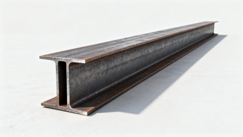
A nominal 8-inch beam depth does not specify the flange width, flange thickness, web thickness, weight per unit length, or steel grade. Sections with similar nominal depths can have different section properties and therefore different bending, shear, and deflection behavior. Depending on the shape family, an I-shaped section may also have dimensions and properties that differ from a similarly sized wide-flange section.
That distinction matters at the receiving dock as much as it does on a calculation sheet. A drawing that says only “8-inch I-beam” leaves too much room for interpretation. The purchase specification should identify the section designation, applicable dimensional standard, material grade, and length, along with any project-specific tolerances or fabrication requirements.
International sourcing adds another opportunity for confusion. A metric section supplied to an EN or GB designation should not be assumed equivalent to a US section merely because its depth converts to approximately eight inches. Compare the actual dimensions, section properties, material requirements, and permitted tolerances. Any substitution needs review and approval against the project requirements before fabrication or installation.
Read the assumptions before reading the capacity
A published beam table normally represents a particular structural model. The figures may be based on a simply supported beam, a specified span, a uniformly distributed load, and stated lateral restraint. They may also reflect a particular design method and deflection limit. Change one of those conditions and the table value may no longer apply.
Start with the table notes and headings, not the largest number in the row. Check whether the listed value is a total load or a load per unit length, whether the beam’s self-weight is included, and whether the load is an allowable service load or a factored design load. A value intended for one design format should not be compared directly with a load calculated in another.
Span also deserves a closer look. A clear opening between walls is not automatically the span used by the table or the engineer. The relevant support locations depend on the actual bearing and structural model. Measuring the opening on site is useful, but it does not by itself establish the design span.
For charts prepared under US practice, the AISC Steel Construction Manual and the applicable AISC specification provide context for section properties and design provisions. Projects governed by Eurocodes or another national system require the appropriate local design basis. A chart from one system is not a shortcut around the requirements of another.
A floor load and a machine load are not interchangeable
Consider a beam selected from a table for an evenly distributed platform load. During installation, a contractor proposes hanging a hoist near midspan. Even if the hoist’s rated load appears smaller than the total distributed load in the chart, the comparison is not enough. A concentrated load produces a different bending and deflection pattern, and the actual demand may include the hoist weight, lifted load, dynamic effects, and attachment forces.
The attachment itself may govern. A clamp, welded lug, or trolley can introduce local flange or web stresses that a simple beam table does not check. Repeated lifting can also raise fatigue questions. Before the hoist is used, the engineer should review the load path from the lifting point through the beam, connections, supports, and foundations, using the applicable design requirements.
The same caution applies to equipment skids, storage racks, suspended pipework, and temporary construction loads. Ask where the load enters the beam, whether it can move, and what else may be present at the same time. A chart value without a load position is not an installation instruction.
Strength is only one part of the check
A beam can satisfy a basic bending-strength check and still be unsuitable. Excessive deflection may damage finishes, affect equipment alignment, or make a floor feel uncomfortable. The acceptable limit depends on the application and project criteria; the limit used by a generic table may be too permissive or unnecessarily restrictive.
Lateral restraint is another common blind spot. The compression flange may need restraint against lateral-torsional buckling. A deck, floor assembly, or secondary member should not be treated as effective bracing simply because it sits near the beam. Its connections, stiffness, spacing, and continuity need to support the assumed restraint.
Near supports and concentrated loads, the web and bearing regions may require separate checks. Short bearing lengths, stiffeners, connection geometry, and the capacity of the supporting wall or column can all matter. A stronger beam does not repair an inadequate support beneath it.
For a warehouse mezzanine, for example, an engineer may need to assess vibration or floor performance as well as strength and deflection. For a beam exposed to fire, corrosion, impact, or elevated temperatures, the project may require additional protection or checks. These issues are not usually resolved by the headline capacity in a chart.
What quality control should verify before release
Treat the chart as a reference document and the approved design package as the controlling document. Before releasing steel for fabrication or installation, reconcile the following items:
- Section identification: Confirm the complete designation and applicable standard on drawings, purchase documents, and material markings. Investigate descriptions that state only nominal depth.
- Material traceability: Match heat or lot identification, where specified, to the mill test documentation. Confirm the ordered grade and required properties rather than relying on a generic “structural steel” description.
- Geometry and condition: Inspect dimensions and visible damage against the purchase and project requirements. Record holes, cuts, welds, corrosion, or deformation that were not included in the approved details.
- Fabrication details: Check connection plates, bolt holes, weld details, stiffeners, bearing lengths, and orientation against the latest approved drawings.
- Document status: Confirm that calculations, drawings, and any substitution approvals refer to the same revision and the same section.
A material test certificate can support identification of the steel supplied; it does not certify that the member is adequate for a particular span or load. Likewise, a beam that matches the purchase order may still be wrong for the project if the order was based on an outdated drawing. Both product conformity and design conformity need attention.
When a substitution appears reasonable
Supply constraints sometimes lead to a proposed alternative with a higher stated yield strength or greater weight per unit length. Neither fact alone proves equivalence. The alternative may have different flange dimensions, connection fit, stiffness, buckling behavior, or material characteristics. A heavier section may solve one concern while creating a clearance or connection problem elsewhere.
Send the proposed section designation, standard, grade, section properties, and available mill documentation to the design engineer. Include the reason for the change and any effect on fabrication or delivery. Keep the response with the project records; a verbal “it should be fine” is difficult to verify after the beam has been concealed.
Hongteng Fengda supplies structural steel beams and other profiles for international projects, where clarifying the specified standard and documentation at quotation stage can help avoid later mismatches. The same discipline applies to other carbon-steel purchases, including Wire Rod: identify the applicable product standard and grade for the intended use rather than assuming that a familiar material description establishes interchangeability. Such material is not a substitute for an approved structural beam.
What to do when the chart is all you have
Do not authorize a new load or installation on that basis alone. Record the chart source and its assumptions, then gather the proposed beam designation and grade, support details, span, restraint, load locations, load combinations, and intended use. If the beam is already installed, document its condition and any alterations; site verification may be needed where markings or records are missing.
Flag uncertain information rather than filling gaps with optimistic assumptions. In particular, do not assume that a connection is pinned, a flange is braced, or a load is uniformly distributed just because those assumptions make the chart easier to use. Refer the information to a qualified structural engineer for review under the applicable project requirements.
If the actual section or support cannot be confirmed, hold the affected work or proposed loading pending direction through the project’s safety process. The useful output is not another capacity number: it is an approved design or documented assessment that states what may be installed, how it must be supported, and what loads it is allowed to carry.
Please give us a message


Please enter what you want to find