A beam weight calculator can disagree with a mill weight because the two figures may describe different things: one is usually a theoretical mass based on nominal dimensions and an assumed density, while the other may be a calculated, tabulated, or physically weighed mass. Rolling tolerances, actual cut length, section geometry, and weighing practice can all contribute to the difference.
When a delivery record does not match the estimate, the first task is not to declare the steel nonconforming. Confirm what each figure represents and put both on the same basis. An unexplained difference can affect receiving records, lifting plans, and structural load assumptions, but a numerical difference alone does not establish a safety or quality failure.
Start by identifying the weight basis
Look at the mill document, purchase order, and calculator output together. A mill weight is not necessarily a scale reading: the document may report theoretical weight from a section table, a calculated weight using nominal dimensions, or actual weight measured for a piece or bundle. The terminology used on the document and the governing order requirements matter more than the column heading alone.
Next, make sure the quantities match. A theoretical value in kilograms per metre must be multiplied by the relevant length and number of pieces before it is compared with a bundle total. Check whether the recorded length is the ordered nominal length, the actual cut length, or a total for multiple pieces. A comparison between one beam and a bundle, or between kilograms and tonnes, can produce a discrepancy far larger than any rolling variation.
For a useful comparison, record the section designation, standard and edition, grade, number of pieces, length basis, calculation method, density, and whether the reported mass is theoretical or actual. If the documentation does not identify the basis, ask the supplier before applying a tolerance or changing the receiving record.
Section geometry is often the first source of disagreement
For a prismatic beam, theoretical mass is calculated from cross-sectional area, length, and density:
Mass = cross-sectional area × length × density.
The formula is straightforward; obtaining an appropriate area is less so. Some calculators use published section properties. Others approximate an I- or H-section as a web and two rectangular flanges. The simplified method may omit root fillets, flange slope, or other profile features included in a standard section table. It can therefore produce a different mass even when the inputs appear correct.
Use a published mass per unit length for the exact section designation and applicable standard where available. Do not assume that profiles with similar depth and width have identical flange thickness, web thickness, or root geometry. Regional naming systems and product series can contain visually similar sections with different nominal masses.
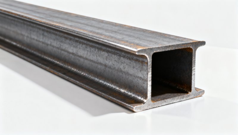
For a fabricated beam or a nonstandard profile, calculate the component volumes from the drawings and agreed dimensions rather than forcing the section into a rolled-beam calculator. Account for additions and removals relevant to the comparison, such as attached plates, weld metal, holes, copes, and end cuts. A preliminary estimate may omit small features, but the calculation record should state those omissions.
Nominal dimensions are not measured dimensions
Rolled sections are manufactured within dimensional and mass tolerances specified by the applicable product and tolerance standards. Actual flange thickness, web thickness, depth, and width can vary from nominal values. Because mass depends on material volume, a small dimensional deviation repeated along the full length can change the total weight.
A beam may be within the permitted dimensional limits while its actual mass differs from a nominal calculator result. Conversely, a total weight that looks close to theoretical does not prove that each critical dimension complies. Excess material in one part of the section can mask a shortage elsewhere, so weight is not a substitute for dimensional inspection.
Measure at the locations and using the methods required by the applicable standard or inspection plan. Avoid drawing conclusions from a single flange-thickness reading taken at an unrepresentative point. Compare the results with the correct tolerance provisions for the ordered section, including any rules governing where measurements are taken.
Density and units can change the result before weighing begins
Many steel weight tools use a conventional density of 7,850 kg/m³. That is a useful calculation assumption, not a measured density for every individual piece. A mill table or another calculator may use a different conventional value or rounding method. Check the density setting and the source of any tabulated unit mass before treating a small difference as a manufacturing issue.
Unit conversion deserves a separate check. For example, an area entered in square millimetres must be converted to square metres when length is in metres and density is in kilograms per cubic metre. Mixing millimetres, metres, pounds, or feet without consistent conversion can generate a substantial error. Rounding the mass per metre before multiplying by a long total length can also create a visible difference in the final total.
A simple numerical illustration helps establish the basis. Suppose a section table gives a nominal mass of 40.0 kg/m and the comparison covers four nominal lengths of 6.0 m. The theoretical total is 40.0 × 6.0 × 4 = 960 kg. This is an arithmetic example, not a tolerance or an expected mill result. If the actual lengths, unit mass, or quantity differ, the comparison must be recalculated using the relevant values.
Actual scale weight has its own boundaries
When the mill figure is physically weighed, establish what was on the scale. A bundle may include straps, spacers, protective material, identification tags, or packaging. The record should make clear whether the stated value is gross or net and whether any tare was measured or estimated. Surface water, debris, or coatings may also affect a scale reading, although their significance depends on the condition and weighing method.
Scale readings are subject to equipment accuracy, resolution, calibration status, operating conditions, and the weighing procedure. A weighbridge total for a shipment should not be compared directly with an individual piece calculation without accounting for the full load and tare. Equally, dividing a bundle weight by the number of pieces gives an average; it does not prove that every beam has that exact mass.
Where the difference is material to acceptance, request the relevant weighing records and clarify the scale resolution and tare method. A repeat weighing may be useful when the procedure allows it, but it should be performed on a suitable verified scale with the same scope of material clearly documented. Repeating a measurement without resolving packaging or quantity differences may simply reproduce the ambiguity.
Work through a discrepancy in a controlled order
- Reconcile the identification. Match the heat or traceability information, section designation, piece count, and delivery documents to the material being checked. Confirm that no mixed lengths or sections are included in the total.
- Recalculate on one basis. Use the same length, quantity, units, section standard, and density or published unit mass. Retain the unrounded intermediate values where practical.
- Separate theoretical from actual mass. Identify whether the mill figure comes from a scale, a section table, or another calculation. Establish whether packaging and tare are included.
- Inspect relevant dimensions. Measure the section and length in accordance with the applicable inspection method. Investigate damage, missing material, or unexpected fabrication separately from normal nominal-to-actual variation.
- Apply the agreed acceptance criteria. Check the purchase order and the applicable product and tolerance standards. Determine whether limits apply to individual pieces, bundles, or another defined quantity; do not assume a general percentage applies to every order.
- Record the disposition. Preserve the calculation inputs, measurement locations, weighing basis, document references, and any supplier clarification. Hold or segregate material when required by the project quality procedure until the discrepancy is resolved.
Calculate the percentage difference only after the comparison basis is aligned: subtract the chosen reference mass from the compared mass, divide by the reference mass, and multiply by 100. State which value is the reference. The percentage is a diagnostic result, not an acceptance limit in itself. Also avoid combining separate dimensional tolerances into a mass limit unless the governing specification explicitly permits that approach.
Distinguish receiving, lifting, and structural decisions
The same weight discrepancy can have different consequences depending on the decision being made. For receiving and invoicing, the contract may specify whether theoretical or actual weight governs. For quality acceptance, the relevant question is whether the material satisfies the ordered standard and documented requirements, not whether two unrelated numbers are identical.
For lifting, do not use a low theoretical estimate as the sole basis when actual load and rigging details are uncertain. Include applicable attachments and lifting gear, establish a reliable load basis, and follow the site lifting procedure and equipment ratings. A bundle average must not be mistaken for the weight of the heaviest individual piece if pieces vary in length or section.
Structural assessment is different again. A scale total does not verify section capacity, material properties, or the adequacy of connections. Dead-load assumptions and member resistance should be assessed using the design documents, applicable provisions, and verified section information. Escalate discrepancies that could affect the approved design or safe handling rather than adjusting design values informally.
When the item is not a rolled beam
Plate and sheet supplied for fabricated sections need a different input method. Rectangular plate mass can be estimated from thickness × width × length × density, with consistent units. Nominal thickness and cutting dimensions still need to be distinguished from actual measurements, and a flat-plate calculation does not automatically include welds, holes, or other fabrication details.
For example, Carbon Sheet Steel is listed in thicknesses from 1 mm to 100 mm and in several widths and lengths. If sheet or plate is being assessed as material for a fabricated component, confirm the ordered grade and dimensions, then calculate each piece on that basis. The listed size range does not establish the actual dimensions or weight of a particular delivery.
Where the remaining difference cannot be explained by matching the inputs, documentation, and measurement scope, retain the original records and seek clarification before closing the nonconformance or changing the declared load. The useful outcome is a traceable comparison: both figures describe the same material, on a known basis, against the requirements that actually govern the order.
Please give us a message


Please enter what you want to find