Does a 12-inch I-beam load capacity chart cover point loads?
Sometimes—but only when the chart explicitly identifies concentrated loads and defines their positions. A 12 inch i beam load capacity chart based on uniformly distributed loading does not automatically approve a machine foot, pipe support, hoist, or other point load. Even a chart labeled “center point load” may cover only global bending and deflection, leaving local flange, web, and connection checks unresolved.
A nominal 12-inch depth alone does not establish capacity. Section designation, steel grade, span, bracing, support conditions, and load location all matter. For beam selection and inspection, the useful question is not simply “How much weight can it carry?” It is “Does this published value describe the beam and load path we are actually building?”
Read the chart’s assumptions before reading its capacity
Start with the diagram, footnotes, and units. “Uniform load” means loading spread along the stated length. “Concentrated load” means a force applied at a defined location, usually idealized as a point for global analysis. A real concentrated load still enters the steel through a finite contact area, and that area matters for local resistance.
Units help, but they are not conclusive. Pounds per foot or kilonewtons per meter usually indicate distributed loading. Pounds, kips, or kilonewtons may describe either a point load or the total distributed load over a span. A heading such as “maximum load” without a loading diagram is insufficient for approval.
- Load arrangement: full-span distribution, central point load, multiple point loads, or another defined pattern.
- Support model: simply supported, cantilevered, or continuous across several supports.
- Capacity basis: allowable service load or design resistance requiring appropriately factored loads.
- Stability assumptions: compression-flange restraint and the specified unbraced length.
- Serviceability: deflection limit and whether the listed value is controlled by strength or deflection.
- Included weight: whether beam self-weight has already been deducted from the available load.
If these details are missing, treat the table as a screening aid, not a release document. Obtain its source and calculation basis rather than trying to reconstruct its assumptions from the numbers.
The same total weight can produce very different bending
Consider an ideal simply supported beam of span L. For a uniformly distributed load w over the full span, the maximum bending moment is wL²/8. If the total distributed load is W = wL, this becomes WL/8. A single load P at midspan produces a maximum bending moment of PL/4.
Therefore, concentrating the same total load at midspan doubles the maximum bending moment. For illustration—not as a beam rating—a 4-kip total load distributed over a 12-foot simply supported span produces 6 kip-feet of maximum moment. Placing all 4 kips at midspan produces 12 kip-feet. Neither number establishes whether a particular 12-inch beam is adequate.
Deflection also changes. Under the same idealized elastic conditions, full-span uniform loading gives a maximum deflection of 5wL⁴/(384EI), while a central point load gives PL³/(48EI). Here, E is the elastic modulus and I is the second moment of area about the bending axis. For equal total load, the central point load causes 1.6 times the deflection.
This is why halving a distributed-load rating is not a complete conversion method. That shortcut addresses one bending comparison under specific assumptions. It does not establish local resistance, stability, connection capacity, or performance under other load positions.
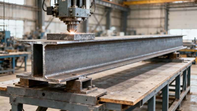
A useful loading sketch should show the support-to-support span, each load position, bearing footprint, and lateral restraints. Those details often reveal a mismatch that a capacity number alone hides.
Moving a point load changes which check matters
For a single load P located a distance a from the left support and b from the right support, with L = a + b, the ideal simply supported reactions are Pb/L and Pa/L. The maximum bending moment occurs beneath the load and equals Pab/L. Midspan is the most demanding location for bending in this particular model.
Moving that load toward a support reduces its maximum bending moment, but increases the reaction at the nearer support. It can also place the concentrated force in a region where end distance and local web behavior become important. “It is close to the column” is not, by itself, a safe reason to accept the load.
Multiple machine feet require their own arrangement. Dividing machine weight equally among four feet is only justified when the equipment data and support behavior support that assumption. An offset center of gravity, unequal support stiffness, operating forces, or installation tolerances can change the individual reactions.
A moving trolley is a different problem again. Its critical position varies along the beam, and acceleration, braking, impact, fatigue, and wheel contact may require additional assessment. A static center-load chart is not a substitute for a lifting-system design.
Global capacity does not settle the load-entry detail
A beam may pass a global bending check yet be unsuitable where the force enters it. A narrow equipment foot on the top flange, a bracket attached to one side, and a hanger beneath the bottom flange do not create equivalent local conditions.
Depending on the detail, engineering checks may include flange local bending, web local yielding, web crippling, and other applicable web limit states. Bearing length, flange thickness, web thickness, distance from the beam end, and force direction affect the assessment. Global shear must also be checked; it is not covered merely because the beam has enough flexural resistance.
A bearing plate can help spread a load, but its dimensions alone do not prove effective distribution. Plate stiffness, actual contact, attachment, and the supporting steel determine how the force transfers. Likewise, adding stiffeners requires a designed detail and suitable fabrication controls—not just a decision to weld extra steel near the load.
Eccentric loading deserves particular attention. A force offset from the web can introduce torsion, while a concentrated load on an inadequately restrained compression flange may affect lateral-torsional stability. A chart assuming continuous lateral support should not be applied to a bare beam simply because both have the same span.
Identify the actual section, not just its depth
“12-inch I-beam” is a commercial description, not a complete engineering specification. A W12 section and an S12 section belong to different section families. Within either family, different weights and flange or web dimensions produce different section properties. Actual depth can also differ from the nominal designation.
For an imported beam, do not accept “equivalent size” as proof of interchangeability. ASTM, EN, JIS, and GB specifications may use different designation systems, dimensional tolerances, and material requirements. A similarly deep section must still be compared against the specified geometry, grade, and design properties.
Higher steel strength does not automatically solve excessive deflection: stiffness depends principally on E and section geometry. Nor does a heavier section automatically eliminate an inadequate support connection. Selection should address the governing problem rather than merely increase beam weight.
Pipe supports show why the complete load schedule matters
A pipe rack may look like a distributed-load application when viewed as a whole, yet individual shoes and hangers introduce concentrated reactions into each beam. Pipe diameter alone cannot define those reactions. Wall thickness, contents, insulation, valves, support spacing, and the piping analysis all influence the loading.
For example, 316 Stainless steel pipe may be specified for chemical-processing or food-production service where corrosion resistance matters. Its material selection does not establish the capacity of the supporting carbon-steel beam. Obtain the installed pipe weight and relevant empty, operating, and test conditions, along with thermal or restraint forces where applicable. The heaviest vertical condition and the governing combined condition may not be the same.
This separation is useful in procurement: pipe conformity, beam conformity, and structural adequacy are related tasks, but none replaces the others.
What to request before accepting the beam selection
Hongteng Fengda, a China-based structural steel manufacturer and exporter supplying beams, channels, angles, cold-formed profiles, and customized components, can support the material and fabrication side of this review. For international orders, however, the purchase specification should identify the required product standard and grade rather than relying on a general statement of standards coverage.
The documentation package should connect the supplied steel to the approved design:
- Exact section designation, dimensions, mass per unit length, and applicable section properties.
- Specified material grade and mill documentation traceable to the delivered material.
- Approved drawings showing spans, supports, bracing, point-load locations, and bearing details.
- Fabrication requirements for holes, welds, stiffeners, plates, and connections, with the specified inspection records.
- The chart’s source and assumptions, or project calculations covering the actual load arrangement and applicable design basis.
A mill certificate supports material identification; it is not a structural capacity certificate. Dimensional inspection confirms the delivered section, but it cannot demonstrate that an unreviewed point-load detail is adequate.
Use a chart to shortlist sections only when its assumptions match the proposed arrangement. If a point load is absent from the chart, its position is undefined, or local bearing and bracing remain unresolved, obtain project-specific engineering review before release for installation. The final acceptance should identify the approved section, load arrangement, and details—not simply record that a “12-inch beam” passed a table lookup.
Please give us a message


Please enter what you want to find