An 8 inch steel i beam load capacity chart can help technical evaluators assess preliminary beam options, but its values depend on more than nominal depth.
Span length, support conditions, load distribution, steel grade, section properties, and deflection limits all influence allowable loads. This guide explains the assumptions behind typical charts.
Use chart values for initial screening, and have a qualified structural engineer verify the final design against applicable codes and project requirements.
What Does an 8-Inch Steel I-Beam Load Capacity Chart Actually Tell You?
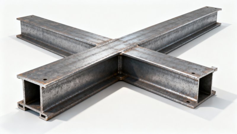
A load chart relates a particular beam section and loading arrangement to a maximum load over a stated span. It is not a universal rating.
For technical evaluation, the first task is identifying whether the chart reports a uniform load, a concentrated load, a reaction, or another quantity.
Next, determine whether the listed value is a service-level load, an allowable load under a specified method, or a factored design resistance.
These quantities cannot be compared directly without checking load combinations and the design method. A chart without that context is unsuitable for final selection.
The term “8-inch beam” generally describes nominal depth, not a unique structural section. Two sections near that depth can have substantially different properties.
For example, a W8×18 and a W8×31 have different weights and section properties. Their capacities also depend on the span and restraint provided.
The following example shows how a chart can be constructed. Its assumed properties are illustrative and are not assigned to a commercial section.
Illustrative Load Chart for a Simply Supported Beam
This example uses a hypothetical, doubly symmetric steel I-section with the properties below. Confirm actual section properties from the applicable manufacturer or steel manual.
- Elastic section modulus, Sx: 20.0 in³.
- Major-axis moment of inertia, Ix: 80.0 in⁴.
- Steel yield strength, Fy: 50 ksi.
- Modulus of elasticity, E: 29,000 ksi.
- Illustrative allowable bending stress: 0.66Fy, or 33 ksi.
- Support condition: simply supported, with no end moment resistance.
- Loading: uniformly distributed service load over the entire clear analysis span.
- Deflection limit: L/360 under that same total service load.
- Compression flange: continuously braced against lateral movement and twist.
The table compares bending and deflection limits only. Values are rounded down slightly and include beam self-weight within the total uniformly distributed load.
One kip equals 1,000 pounds. At 15 feet, the lower value represents approximately 1,010 pounds per foot of total uniformly distributed service load.
If the selected beam weighs 25 pounds per foot, subtract that weight before allocating the remaining approximately 985 pounds per foot to other uniform loads.
That subtraction does not establish a safe project capacity. Shear, stability, bearing, connections, local section behavior, and applicable code requirements remain unchecked.
The example also assumes the same L/360 limit applies to total load. A project may instead specify different limits for live and total deflection.
How Are the Chart Values Calculated?
For a simply supported beam carrying a uniform load, maximum bending moment is wL²/8, where w is load per unit length and L is span.
The illustrative bending moment limit is 0.66FySx. With the assumed properties, that equals 660 kip-in, producing a bending limit of 4.40 kip/ft at 10 feet.
For the same beam and loading, maximum elastic deflection is 5wL⁴/(384EIx). Setting that deflection equal to L/360 gives the table’s deflection limits.
Use consistent units when applying either equation. For example, calculate with inches, kips, and ksi, then convert the resulting load to kip per foot.
These equations explain why span matters so strongly. The bending-based uniform load falls with span squared, while the L/360 deflection-based load falls with span cubed.
Doubling the span from 10 to 20 feet therefore reduces the illustrative bending limit to one-quarter and the deflection limit to approximately one-eighth.
This calculation is an educational screening example, not a complete implementation of a structural design standard. Actual allowable strength depends on additional section and stability checks.
Which Span and Support Conditions Apply?
Charts commonly assume simple supports at both ends. The analysis span is the distance used in the structural model, often between support centerlines.
Do not automatically substitute the clear opening between walls. Bearing dimensions, connection geometry, and the governing design standard may affect the appropriate model.
A simply supported beam can rotate at its ends and generally develops no end moments in the idealized analysis. Real connections may behave differently.
A fixed-end beam, continuous beam, and cantilever have different moment and deflection patterns. Their capacities cannot be obtained by relabeling this table.
Continuity over multiple supports can reduce some span moments but introduces negative moments, support reactions, and connection demands that also require verification.
Similarly, a cantilever must resist moment at its fixed support. The adequacy of that support and its connection is essential to the analysis.
For preliminary comparison, record the actual support arrangement, bearing lengths, restraint details, and whether adjacent spans provide structural continuity before selecting a chart.
How Does Load Distribution Change Capacity?
A uniformly distributed load is spread along the span. Floor joists or decking may approximate this condition when their loads are transferred regularly.
A concentrated load acts over a short length, such as a column reaction or equipment support. It produces a different moment and deflection response.
For a single load P at midspan of a simply supported beam, maximum moment is PL/4 and maximum deflection is PL³/(48EIx).
Using the example properties at 15 feet, bending limits that centered load to approximately 14.66 kip; L/360 limits it to approximately 9.54 kip.
Those figures are for the centered load acting alone. Beam self-weight and other loads must be included through appropriate combined analysis, not ignored.
A load near one support changes the reaction distribution and moment location. Multiple point loads, moving loads, and partial-span loads likewise need separate analysis.
Point loads can also cause local flange bending, web yielding, web crippling, or connection failures. A global bending calculation alone will not capture them.
Why Do Steel Grade and Beam Properties Matter?
Steel grade influences strength, but nominal depth does not define grade, flange dimensions, web thickness, section modulus, or moment of inertia.
For elastic bending, a larger section modulus generally increases moment capacity when other governing conditions remain unchanged. Actual design strength depends on the applicable standard.
Moment of inertia governs elastic deflection. Increasing yield strength alone does not materially reduce deflection when the beam geometry and elastic modulus remain unchanged.
That distinction matters when a chart is deflection-controlled. Substituting higher-strength steel without changing the section may add strength but leave serviceability unchanged.
Section dimensions also affect shear, local buckling, connection detailing, and torsional behavior. Obtain published properties for the exact section and orientation being evaluated.
Confirm whether the beam bends about its major or minor axis. A section rotated from the assumed orientation can have substantially different stiffness and strength.
When comparing ASTM, EN, JIS, or GB products, match dimensions, material properties, tolerances, and design rules rather than treating similarly named grades as interchangeable.
What Can Reduce the Usable Load?
Lateral-torsional buckling can reduce bending resistance when the compression flange lacks adequate restraint. A floor or deck provides restraint only when its details justify that assumption.
Bracing spacing, bracing strength, load application position, and connection details affect stability. The continuous restraint assumed in the example must be demonstrated in practice.
Shear may govern for short spans or heavy concentrated loads. Web openings, copes, and corrosion can further reduce the available resistance.
Bearing and support conditions deserve separate attention. A beam may resist the calculated span moment while its web or supporting material cannot carry the reaction.
Connections must transfer vertical reactions and any required lateral or axial forces. Bolts, welds, plates, and supporting members need their own checks.
Serviceability may also govern through vibration, floor movement, finishes, or equipment alignment. An L/360 calculation does not automatically address those requirements.
For existing structures, verify actual dimensions, material condition, modifications, and load path. Do not assume the original drawings represent the beam’s current capacity.
How Should Technical Evaluators Compare Supplier Charts?
Start by requesting the exact section designation, dimensional standard, steel grade, and published section properties. Check whether values are calculated about the intended axis.
Then compare span definitions and support conditions. Charts based on different end restraints or unbraced lengths are not directly comparable, even for identical sections.
Check the load basis carefully: pounds per foot and total pounds over the span describe different quantities. Confirm whether beam self-weight is included.
Identify the design method and governing load combinations. Allowable-strength tables and factored-resistance tables must not be mixed without the relevant code framework.
Review deflection criteria and load categories. A chart limited to live-load deflection may permit a different total load from one limited by total-load deflection.
Ask whether the chart includes shear, lateral-torsional buckling, bearing, and connection checks. An omitted check is not evidence that the condition is acceptable.
Finally, request traceable material documentation and confirm availability, tolerances, delivery lengths, and fabrication requirements before using a proposed section in procurement planning.
Where Do Sheet Piles Fit in a Steel Procurement Package?
Some projects require both structural beams and retaining systems. These products serve different structural functions and should be evaluated using separate design assumptions.
For retaining or water-retaining walls, Hongteng Fengda offers Hot Rolled Steel Sheet Pile in U-shaped configurations, with project-specific lengths available for discussion.
Listed material options include S275, S355, SY295, SY390, and ASTM A690. Confirm the selected grade, section, interlock, and applicable standard for each order.
Sheet-pile design also requires assessment of soil and water pressures, embedment, interlocks, and construction conditions. An I-beam load chart does not address those factors.
Final Checklist Before Selecting a Beam
An 8-inch nominal depth is a starting point, not a capacity. Select an exact section and use chart values only when their assumptions match.
Document the span, supports, load pattern, restraint, steel grade, self-weight, and deflection criteria. Treat missing assumptions as unresolved design questions.
Have a qualified structural engineer verify strength, stability, serviceability, supports, and connections under the applicable code before approving the beam for construction.
Please give us a message


Please enter what you want to find