Misalignment during installation is usually visible before the connection is fully closed: bolt holes drift away from each other, a beam flange will not seat on its support, brace ends pull a frame out of plumb, or a column line moves as temporary bolts are tightened. These symptoms should not be treated as isolated fitting problems. Forcing members into position with drift pins, oversized wrenching, heat, or excessive crane pressure can transfer the error into another connection and leave residual stress in the assembled frame.
The practical response is to identify where the dimensional chain first departed from the intended geometry. A structural frame accumulates small variations from shop layout, cutting, drilling, welding, handling, foundation setting-out, and erection sequence. A small error at one interface may be harmless; the same error repeated across several bays can prevent the final connection from aligning. The most useful investigation starts with the primary reference points rather than the hole that happens to be inaccessible.
Fabrication dimensions that do not match the controlling references
Steel members are fabricated from reference lines, work points, end faces, centerlines, and connection gauges. Misalignment occurs when the shop dimension is technically correct in isolation but is taken from a different datum than the erection drawing uses. For example, a beam may have the correct overall length while its end-plate bolt pattern is offset from the required column centerline. The beam then appears too long or too short at installation even though a tape check of its length gives an acceptable result.
End preparation deserves close attention. A saw cut that is not square, an incorrectly located cope, or an end plate attached slightly out of position changes how the member bears against its mating part. On a short member, this may only create a local gap. On a long rafter or beam, a small angular difference at one end shifts the far connection enough to make bolt insertion difficult.
Curved, cambered, tapered, or built-up members require different judgment from straight rolled sections. Their measured length changes with the reference path used. Measuring along a flange edge, along the neutral line, or between projected work points can produce different values. A member should be assessed against its stated control points, not against a convenient edge that was never intended to govern fit-up.
Hole position and hole condition
Incorrect hole location is a direct cause of installation trouble, but the apparent problem is not always caused by drilling. Holes can seem misplaced when a connected plate has rotated during welding, when a support is not level, or when a member is installed on the wrong face of a symmetrical-looking connection. Before reaming or enlarging a hole, compare the complete bolt group against the drawing dimensions, including edge distances, gauges, and the member orientation.
Hole quality also affects alignment. Burrs, distortion around punched holes, weld spatter, paint build-up, or damage from transport can reduce the effective clearance. A bolt that starts in one hole but stops at the next may indicate that the holes are nearly aligned but obstructed, whereas a drift pin that enters only at a pronounced angle points to a positional or rotational error. These conditions need different corrections.
Do not use the first bolt that enters as proof that the connection is correctly positioned. A connection can pivot around one loose bolt and conceal a mismatch elsewhere. Bring the member into the specified line and elevation, insert enough temporary bolts to hold the geometry, and then verify the remaining holes before final tightening.
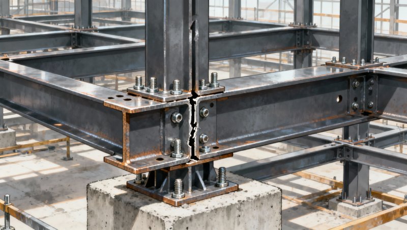
Welding distortion that changes connection geometry
Welding introduces localized heating and shrinkage. If a connection plate is welded on one side of a member without balanced restraint or sequence, it may pull toward the weld and change both position and angle. This is especially noticeable on thin plates, cold-formed profiles, built-up members, and bracket connections with eccentric welds. The member may leave the fabrication fixture apparently acceptable, then relax after unclamping or cooling.
Distortion is often misread as a drilling error because the bolt pattern is the first feature that fails to align. A simple comparison of diagonal dimensions across the plate can reveal whether the plate has racked. Checking the plate face against the member web or flange can show rotation. Where the connection is part of a welded assembly, correcting only the holes may leave the bearing surfaces out of contact and create a more serious fit-up issue.
Heat straightening should not be used as an improvised site adjustment. It changes the member through controlled thermal work and needs an approved method that considers section thickness, restraint, connection details, and the effect on coatings. Uncontrolled heating near high-strength bolted joints, welds, or thin elements can create damage that is harder to detect than the original misalignment.
Member identification and orientation errors
Many installation problems arise from using the right-looking member in the wrong location. Frames commonly contain beams of similar depth with different end connections, handed brackets, varying cope dimensions, or small changes in bolt gauge. A reversed member can place holes on the wrong side of the work line even when its length and section match the drawing.
Marks should remain readable through blasting, priming, storage, and transport. If an identification mark is lost, do not rely only on visual similarity. Confirm the member mark, section size, connection configuration, and orientation against the erection drawings. Where a detail is handed, establish a consistent viewing direction before deciding whether it is left- or right-handed. Confusion at this point can lead to unnecessary grinding or field modification of a component that was fabricated correctly.
Column base plates create a related problem. A column may be positioned with the correct grid intersection but rotated by 90 degrees, placing moment-connection flanges or brace gussets in the wrong direction. Checking only the anchor rod pattern is insufficient when the pattern is square or nearly symmetric. The column orientation mark, major-axis direction, and connection faces must agree before the nuts are brought down.
Foundation and support conditions that mimic steelwork errors
When several members around one area refuse to fit, the support geometry should be checked before blaming every steel component. Base plate elevation, anchor rod spacing, pedestal location, bearing seat level, and embed plate position all control the starting point of the frame. A column installed over uneven shims or a sloping grout surface may be plumb at one point yet carry its beam seat at the wrong elevation.
Anchor rods are particularly sensitive because they are fixed before the steel arrives. Rods can lean, shift during concrete placement, or emerge with damaged threads. An anchor pattern may accept the base plate initially but prevent final adjustment once washers and nuts are installed. The proper assessment includes the rod center positions, verticality, projection, thread condition, and the actual base plate hole arrangement. Altering holes without reviewing edge distance and load transfer can compromise the intended connection.
Support-level errors often create a recognizable pattern. If both beam ends are consistently high or low relative to their columns, investigate elevations. If one end fits in plan but the opposite end twists, look for column rotation, support skew, or a member orientation issue. If the problem grows across consecutive bays, verify grid control and the first installed frame rather than adjusting each later beam independently.
Handling damage and uncontrolled temporary restraint
Long slender members can deform during lifting, storage, or transport. A beam supported only near its ends can sag; an open channel can twist; a light truss can rack if lifted from points that do not match its planned lifting arrangement. Permanent deformation is not always obvious while the member is suspended or resting on uneven ground. Once connected, the distortion appears as misaligned holes or an unexpected gap at a bearing point.
Inspect connection plates, flange edges, and brace ends after unloading. Forklift contact, chain impact, and stacking pressure frequently damage the parts that establish alignment. Minor coating damage is distinct from a bent plate or crushed hole edge. A straightedge, square, and measured diagonals give more useful evidence than a quick visual judgment.
Temporary braces and erection bolts should hold the frame without pulling it away from its surveyed position. Tightening a brace to make one connection close can rack adjacent bays. Likewise, removing temporary support too early allows a partially connected assembly to move under its own weight or under wind. The frame needs enough stable connections to maintain line, level, and plumb while the next members are introduced.
Connection sequence and the effect of accumulated tolerance
Installation sequence has a large influence on whether normal fabrication variation remains manageable. Starting from a surveyed control bay and stabilizing it before extending the frame gives later work a reliable reference. Building several loosely connected bays and attempting to pull the far end into position later often concentrates all accumulated variation at the last splice or roof connection.
Connections with slotted holes, shims, pack plates, or site-adjustable details must be used in the direction intended by the design. A slot provides adjustment along one axis, not unlimited correction in every direction. Filling a gap with an unapproved stack of washers, omitting required pack plates, or tightening before the member is seated changes the connection geometry and may leave bolts loaded in an unintended manner.
Diagonal checks are useful for rectangular braced frames because unequal diagonals indicate racking. They are less decisive for irregular geometry, cambered roof members, or frames with non-orthogonal grids. In those situations, use the project control points, specified offsets, and survey coordinates. A frame can have matching diagonals and still be displaced from its intended grid line.
Separating a local issue from a system error
A single connection that will not close after nearby members have been surveyed may be a local fabrication, damage, or identification issue. A recurring offset at every similar connection suggests a drawing interpretation, gauge, or reference-datum problem. The distinction matters because local field work on a system error creates inconsistent corrections across the structure.
Record measured offsets before any modification. The record should identify the relevant grid lines, elevation, member mark, connection face, hole positions, and whether the frame was fully supported when measured. Photographs alone rarely establish whether the error is in plan, elevation, rotation, or member shape. Clear measurements prevent the same issue from being repeatedly diagnosed from different assumptions.
Structural steel assembly also interacts with reinforced concrete work at interfaces such as column pedestals, transfer elements, and composite construction. Where high-strength reinforcing steel is specified, such as HRB600 Rebar, reinforcement congestion and bar placement should be coordinated before concrete is placed around anchor assemblies or embedded plates. The reinforcing bar itself does not correct steel alignment; its relevance is maintaining the designed concrete and embed geometry so that anchors and bearing surfaces remain where the steel connection expects them.
Correcting misalignment without creating a larger defect
First establish whether the member is safe to release, support, or reposition. Then loosen only the connections needed to restore the intended geometry, using survey references rather than the nearest accessible hole. Temporary bolts and approved erection aids can guide a correctly aligned joint into place, but they should not be used to force a member that is visibly bent or incorrectly fabricated.
Field reaming, slotting, cutting, welding, or adding plates changes the connection and requires review by the responsible engineering authority. The need for approval is especially clear where a change affects bolt edge distance, net section, weld access, bearing, slip resistance, fatigue-sensitive details, fire protection, or corrosion protection. A quick alteration may make the bolt fit while reducing the connection's intended capacity or durability.
Once the correction is complete, recheck the surrounding frame. Alignment is a geometric condition shared by connected members, not a property of one repaired hole. Confirm line, level, plumb, bearing contact, bolt engagement, and the condition of any temporary restraints before proceeding to final tightening or the next erection stage.
Please give us a message


Please enter what you want to find