Understanding the safe working load (SWL) for 12mm steel wire rope is not a single-value answer—it’s a function of material strength, construction configuration, termination method, environmental exposure, and the safety factor applied to the ultimate tensile strength (UTS). For field personnel engaged in lifting, rigging, or temporary structural support—especially on construction sites where dynamic loads, abrasion, and bending over sheaves are routine—the SWL directly governs whether a lift proceeds safely or introduces unacceptable risk.
The nominal diameter of 12mm refers only to the rope’s outer envelope—not its actual load-bearing cross-section. A 6×19 class wire rope with fiber core (FC), for example, has significantly less metallic area than a 6×37 IWRC (independent wire rope core) variant of the same diameter. That difference alone can shift the UTS by over 25%. Standardized UTS values for common grades are: approximately 1,570 MPa for Grade 1570, 1,770 MPa for Grade 1770, and up to 1,960 MPa for premium high-tensile grades. But UTS is not operational capacity—it is the theoretical breaking point under ideal laboratory conditions. Real-world performance degrades due to kinking, corrosion, fatigue from repeated bending, and improper spooling.
How SWL Is Calculated—and Why It Varies
The fundamental formula is straightforward: SWL = UTS ÷ Safety Factor. Yet the variables feeding that equation are rarely fixed. The safety factor itself depends on application class: 3.5–5.0 for general engineering lifts; 6.0–8.0 for personnel hoisting; and as high as 10.0 for permanent suspension systems where inspection access is limited. A 12mm Grade 1770 6×37 IWRC rope may have a published UTS of ~122 kN. Applying a safety factor of 5 yields an SWL of 24.4 kN—or roughly 2,490 kg. But if the same rope is bent around a 120mm-diameter sheave (D/d ratio = 10), its effective strength drops by ~15% due to internal wire stress concentration. Now the usable SWL falls to ~21.2 kN. If it’s also subjected to frequent wet or saline exposure without proper lubrication, corrosion pitting further reduces cross-sectional integrity—potentially by another 10–20% over six months of intermittent use.
Termination method critically influences real-world capacity. A thimble eye splice retains ~90–95% of the rope’s UTS. A wedge socket or swaged sleeve may achieve 95–100%, but only if installed precisely per manufacturer torque and compression specs. A simple clip-and-U-bolt (e.g., three clips spaced at 6× rope diameter) retains only ~80%—and that assumes correct orientation (saddle on live end) and re-torque after initial loading. Misapplied clips are among the most common causes of premature failure in field-rigged 12mm assemblies.
Construction Type Matters More Than Diameter Alone
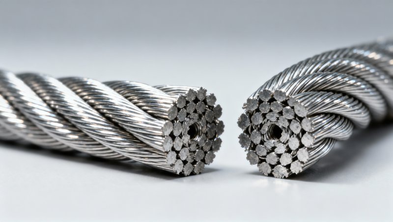
A 12mm diameter conceals major internal differences. Compare these typical configurations:
- 6×19 FC: Fewer, thicker wires—higher resistance to abrasion and crushing, but lower flexibility and fatigue life. Common in static guy lines and crane pendant applications where bending cycles are minimal.
- 6×37 FC/IWRC: More, finer wires—greater flexibility and fatigue resistance, but more vulnerable to surface wear and distortion under side loading. Preferred for hoist ropes running over multiple sheaves.
- 8×19 or 8×25 Seale: Compromise design offering improved rotation resistance and better load distribution across strands—often used in winch lines and marine applications where torque-induced kinking must be minimized.
None of these share identical SWLs—even at identical grade and diameter. A 12mm 6×37 IWRC Grade 1770 rope typically carries ~5–8% higher SWL than its 6×19 counterpart under identical safety factors and termination methods. That margin disappears, however, if the 6×37 rope runs over a worn or undersized sheave groove, accelerating outer wire breakage.
Environmental and Operational Limits You Can’t Ignore
Temperature extremes affect both tensile properties and lubricant viscosity. Below −20°C, standard grease stiffens, increasing inter-wire friction and reducing fatigue life. Above +80°C, polymer-based lubricants soften or migrate, exposing bare wires to oxidation. In such environments, SWL should be derated by 10–15% unless the rope is specifically heat- or cold-rated.
Chemical exposure is equally consequential. Sulfur compounds (common near geothermal or wastewater infrastructure) accelerate hydrogen embrittlement in high-strength steels. Chloride-laden atmospheres—coastal or de-icing salt environments—induce pitting corrosion that initiates subsurface cracks undetectable by visual inspection. In these cases, regular magnetic particle testing becomes essential, and SWL assumptions based solely on new-rope UTS become invalid after even moderate service time.
Mechanical damage often goes unrecorded until failure. A single impact against a sharp edge can nick multiple outer wires, reducing local strength by 30% or more. A rope showing no visible distortion but exhibiting stiffness or “grittiness” when flexed likely has internal wire fractures—a condition that cannot be quantified without non-destructive testing, yet demands immediate removal from service.
Integration With Structural Systems
In composite applications—such as anchoring temporary bracing or stabilizing excavation shoring—the interaction between wire rope and connected structural elements determines system-level capacity. For instance, when a 12mm wire rope is tensioned to stabilize a Hot Rolled Steel Sheet Pile wall, the rope’s SWL must align with the pile’s pull-out resistance, the anchor embedment depth, and the connection hardware’s shear rating. Over-specifying the rope while under-designing the anchor bolt or weld detail creates a false sense of security. Field verification of all interface points—not just rope selection—is mandatory.
Verification and Maintenance Protocol
Relying solely on catalog SWL tables invites error. Best practice requires on-site verification through three parallel checks:
- Visual inspection before each shift: Look for broken wires (>2 in one strand or >4 in one lay), severe kinking, birdcaging, or core protrusion.
- Diameter measurement at three locations: Using a calibrated vernier caliper—not a tape measure. A reduction of >5% from nominal 12mm indicates significant internal degradation, regardless of visible breaks.
- Load history tracking: Document number of lifts, estimated load magnitudes, and bending cycles. Ropes subjected to repeated shock loading (e.g., dropping loads onto slings) require replacement well before visual wear thresholds are reached.
No single parameter defines safe operation. It is the convergence of correct grade selection, appropriate construction for the duty cycle, verified termination integrity, environmental adaptation, and disciplined inspection discipline that sustains reliable performance. When any one element deviates—whether a mismatched sheave, overlooked corrosion, or undocumented impact damage—the calculated SWL becomes irrelevant. What remains is the physical reality of the rope in hand, under load, at that moment.
Please give us a message


Please enter what you want to find