A36 structural steel is generally straightforward to weld, but a sound joint still depends on more than choosing a compatible electrode. Dirty surfaces, poor access, unsuitable parameters and uncontrolled restraint can produce defects even when the steel itself is readily weldable. Before striking an arc, establish the required weld, joint geometry and approved welding procedure; then check that the parts and working conditions match them.
For operators, the most useful approach is to connect each visible symptom to the conditions that created it. Porosity calls for a different correction from incomplete fusion, while cracking requires the weld to be stopped and assessed rather than simply covered with another pass. The guidance below supports that diagnosis; project drawings, the applicable code and the welding procedure specification (WPS) govern the work.
Start with the joint, not the machine settings
Check the drawing for weld type, size, length and location. A fillet weld on a lap joint has different access and inspection requirements from a groove weld in a heavily restrained butt joint. Confirm that the joint preparation, root opening and fit-up agree with the approved details before tacking. A gap that varies along the joint makes it harder to maintain consistent penetration; forcing misaligned parts together can add restraint and make distortion harder to control.
Clean the weld area and the adjacent surface where the arc and shielding gas will operate. Remove oil, moisture, loose scale, rust, paint and other contamination as required by the procedure. Pay attention to both sides of a joint where backing, back gouging or welding from the reverse side is specified. A surface can look acceptable from the operator’s side while trapped contamination at the root creates trouble later.
Coated steel needs particular care. Remove the coating from the weld area in accordance with the job requirements, and use suitable ventilation and respiratory protection as required by the workplace safety assessment. Zinc fumes from galvanized material are hazardous. After welding and inspection, restore corrosion protection using the specified repair system; bare weld areas should not be left exposed simply because the surrounding steel is coated.
Keep fabrication wire separate from welding consumables when organizing materials. For example, Premium Galvanized Cold Drawn Steel Wire Rod (1.6mm - 6mm) is galvanized wire for industrial uses; its presence on a fabrication site does not make it a suitable filler for an A36 structural joint. Use only the filler metal and consumable classification permitted by the WPS.
Recognize the defect before changing the process
Surface appearance provides useful clues, but it does not reveal every internal discontinuity. A neat-looking bead can still contain lack of fusion or incomplete joint penetration. Equally, spatter or an uneven profile may signal unstable technique without proving that the joint has an internal defect. Use visual observations to guide investigation, then apply the inspection method specified for the joint.
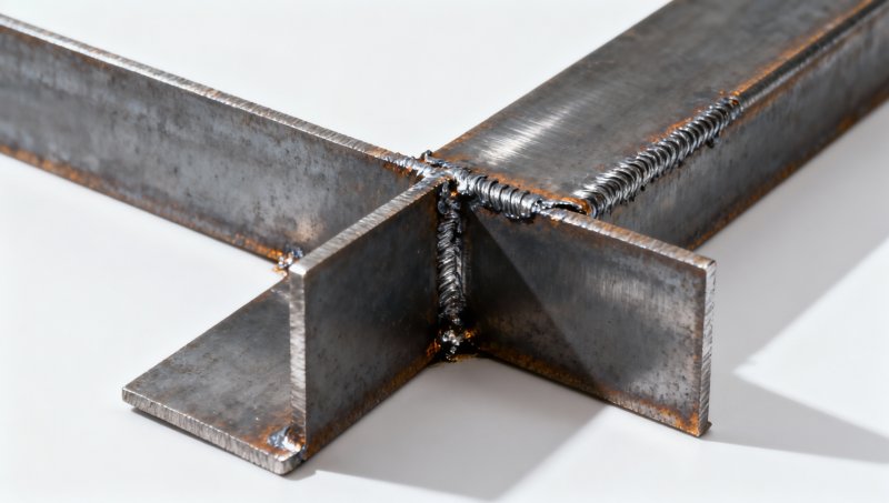
Porosity: look beyond the holes
Porosity appears as cavities in the weld metal, sometimes visible on the surface and sometimes found only through testing. Contamination and moisture are common contributors, but a clean plate alone will not solve a shielding problem. With gas-shielded processes, check for drafts, damaged hoses, loose connections, a blocked nozzle and the gas flow specified for the setup. Excessive flow can also disturb shielding, so increasing the flow without diagnosis is not a reliable fix.
Consumable condition matters as well. Follow the manufacturer’s storage and handling instructions and the WPS, particularly for low-hydrogen electrodes and fluxes. Damp or damaged consumables should be handled under the site’s reconditioning or disposal rules, not dried by guesswork. For self-shielded or flux-covered processes, verify that the consumable, polarity and technique match the procedure.
If pores appear repeatedly in the same area, examine the joint surface and fit-up there before grinding and rewelding. Oil can remain in tight overlaps, and moisture can collect on cold steel. Remove defective weld metal as required, eliminate the cause and inspect the repair under the applicable acceptance criteria.
Incomplete fusion and penetration: check access and heat placement
Lack of fusion occurs when weld metal fails to fuse adequately with the base metal or a previous weld pass. Incomplete joint penetration concerns the extent to which a groove weld reaches through the joint thickness; whether full or partial penetration is required comes from the joint design. Neither condition should be judged solely by how large the finished bead looks.
Restricted access, an unsuitable work angle, travel that is too fast, or parameters outside the WPS can leave a sidewall or root insufficiently fused. In multipass welding, slag or other residue left between passes can create the same problem. A narrow groove may make it difficult to direct the arc to the sidewalls, particularly if the electrode or gun cannot reach the intended position.
Correct the fit-up and access first. Then use the specified range of parameters and direct the arc so the weld pool wets the required surfaces. Remove slag between passes and inspect the exposed surfaces before continuing. Do not compensate for a joint outside its permitted dimensions by depositing a larger cap: the visible reinforcement cannot establish fusion at a hidden root.
Undercut, overlap and an inconsistent profile
Undercut is a groove melted into the base metal at the weld toe and left unfilled. Excessive travel speed, unsuitable arc manipulation or parameters, and poor work angle can contribute. Overlap occurs when weld metal rolls onto the base metal without proper fusion. In either case, look at the weld pool and how it joins the parent metal rather than concentrating only on bead width.
Adjust technique and settings within the WPS, and maintain an angle that provides access to both sides of the joint. On fillet welds, check that both legs meet the drawing requirements; a convex bead is not proof of adequate throat or fusion. Use a suitable weld gauge where dimensions must be verified, and compare the profile with the applicable acceptance criteria.
Cracking requires a different response
A visible crack is a stop point. Mark the location, notify the responsible supervisor or welding coordinator and preserve enough information to investigate the joint and procedure. Grinding off the visible line and welding over the area can conceal a crack that extends below the surface.
Cracking can be influenced by hydrogen, restraint, joint thickness, cooling conditions, weld metal selection and the composition of the material being joined. A36 designation alone does not establish that every assembly can be welded without preheat. The WPS and applicable code determine whether preheat and interpass temperature controls are required for the actual material, thickness, process and service conditions.
Check temperature at the locations and times specified by the procedure using an appropriate temperature-indicating method. Maintain the required temperature through the welding sequence, and do not assume that warming only the immediate surface is sufficient. Low-hydrogen practice also depends on clean, dry joint surfaces and properly controlled consumables.
The repair plan should establish the extent of cracking, the removal method, any required examination before rewelding, and the procedure for the repair. Depending on the joint and code, inspection may also be required after a specified interval. Those decisions belong to the responsible welding and inspection personnel, not to an improvised shop-floor repair.
Control distortion before it becomes a fit-up problem
Welding heats and cools the joint unevenly, so some movement is expected. Thin members, long welds and assemblies with poor balance can be especially sensitive. A component may meet its weld-size requirement yet fail dimensional checks because the sequence pulled it out of alignment.
Plan the sequence before completing the first long pass. Secure parts with suitable fixtures and properly sized tack welds, check alignment, and follow the approved sequence for distributing welds around the assembly. Where the procedure permits, alternating sides or dividing a long weld into shorter sections can help balance shrinkage. Clamps can limit movement during welding, but releasing them may reveal residual distortion, so check the assembly after restraint is removed.
Avoid depositing more weld metal than the drawing requires. Oversized fillet welds add heat and can increase distortion without resolving a poor fit-up. Conversely, skipping required weld length or reducing weld size to limit movement changes the joint capacity and needs engineering approval. If distortion is already outside tolerance, use the project’s approved correction method rather than applying uncontrolled heat or force near completed welds.
Build inspection into the welding sequence
Inspection is most effective when it starts before the joint is closed. Once a root is covered by later passes, direct visual access may be lost. At practical hold points, the operator can check:
- Before welding: material identification, joint preparation, cleanliness, fit-up, tack quality and access.
- During welding: consumable condition, shielding, specified temperature controls, interpass cleaning and the appearance of each accessible pass.
- After welding: weld location, length, size, profile, visible discontinuities and final alignment.
Visual inspection does not replace nondestructive testing when the drawing or code requires it. The appropriate method and acceptance criteria depend on the joint and project requirements. For example, an internal discontinuity may require a different examination method from a surface-breaking indication; the inspector should make that determination under the applicable procedure.
When a defect recurs, record where it appears and what was happening immediately before it appeared: joint position, pass, consumable, settings, fit-up and environmental conditions. Change one relevant condition at a time where practical and stay within the approved WPS. That gives the operator and welding coordinator a clearer basis for correcting the cause rather than repeatedly repairing the same joint.
Please give us a message


Please enter what you want to find