Structural Steel Drilling: Hole Tolerances That Protect Connection Performance
Structural steel drilling is more than making holes—it is a critical step in protecting connection strength, alignment, and long-term project safety. A hole that appears only slightly misplaced or oversized can create bolt fit-up problems, force site modifications, reduce bearing performance, or delay erection while teams decide whether a repair is acceptable. For operators, the most useful mindset is simple: every drilled hole is part of a connection system, not an isolated machining feature.
The required result is not merely “a bolt can pass through.” The hole must be the correct type, diameter, location, shape, edge condition, and orientation for the bolt assembly and connection design. Those requirements may come from contract drawings, fabrication specifications, governing steelwork standards, and approved shop drawings. ASTM, EN, JIS, and GB projects can use different terminology and acceptance conventions, so the released project documents—not habit from a previous job—must control the work.
Why Hole Tolerance Has a Direct Effect on the Connection
Bolted structural connections transfer load through several mechanisms. Depending on the design, the bolt may work in bearing, slip resistance, tension, or a combination of these actions. Hole geometry influences how the connected parts come together and how force enters the plate, beam flange, angle, channel, or gusset. A poor hole pattern can also introduce unintended eccentricity, making a connection behave differently from the detail that was designed.
An oversized hole is not automatically defective. Standard specifications recognize several hole categories, including standard round holes, oversized holes, short-slotted holes, and long-slotted holes. Each category has a purpose. Slots may allow for movement, erection adjustment, or thermal effects, but their direction and use must be specified. Substituting a larger hole simply because a component did not align is not the same as using an approved oversized or slotted hole in a designed connection.
Location tolerance matters just as much. If one hole is shifted, a single bolt may still enter. If an entire group has drifted, the member may need to be pulled into position, which can distort connected steel, increase installation stress, or make adjacent components impossible to fit. In repetitive framing, small layout errors can accumulate until the issue becomes visible only at erection.
Hole quality also affects practical performance. Heavy burrs prevent proper faying-surface contact. Torn edges, work-hardened surfaces, excessive heat discoloration, or out-of-round holes can complicate inspection and bolt installation. A drilled hole should be clean and true to the specified geometry, with burrs removed where required, rather than treated as acceptable because it is hidden after assembly.
Read the Drawing Before Setting Up the Drill
Most preventable drilling errors start before the tool touches the steel. Operators should confirm the member mark, drawing revision, connection face, datum points, hole type, bolt designation, and any instruction related to coating, welding sequence, or site-fit conditions. On asymmetrical members, it is especially easy to drill the correct pattern on the wrong face. Angles, channels, tee sections, and built-up members need clear orientation control.
Do not assume that nominal bolt size equals nominal hole size. The applicable design and fabrication requirements define the permitted hole dimensions and any special treatment for slots. They may also define tolerances for hole spacing, end distance, gage, and the relative position of matching holes. Where project documents conflict or leave uncertainty, the issue should be resolved through the responsible engineering or quality process before production proceeds.
A useful pre-drilling check is to identify the feature that actually controls the pattern. It may be a beam end, the centerline of a web, a flange edge, a plate datum, or the center-to-center relationship between holes. Measuring every hole independently from an outside edge can magnify layout variation. Datum-based measurement keeps the pattern tied to the design intent.
- Verify the latest approved drawing and member identification.
- Confirm whether holes are standard, oversized, short-slotted, or long-slotted.
- Check bolt diameter and grade against the connection schedule.
- Establish the correct reference face and primary datum.
- Review any restrictions on field modification or flame cutting.
The Tolerances That Need Attention on the Shop Floor
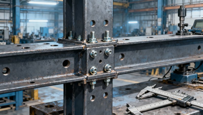
Hole diameter is the most obvious control, but it is only one. A reliable inspection routine considers diameter, center location, spacing, slot dimensions, hole axis, and edge condition. The applicable standard or project specification should provide the acceptance basis. Operators should not use a universal “shop tolerance” for every export project, because bolt systems, connection categories, and client specifications can vary.
The hole axis deserves attention when drilling thick material or stacked plies. A drill that wanders, a poorly secured workpiece, or a worn magnetic drill base can create a hole that is not perpendicular to the contact surface. The bolt may still pass through, but washers may not seat evenly and matching components may resist assembly. This risk rises when drilling close to edges or across uneven surfaces.
Drilling Method Changes the Risk Profile
CNC drilling lines, radial drills, magnetic drills, punch systems, and thermal cutting equipment can all be used in structural fabrication under appropriate controls. The question is not which process sounds most advanced; it is whether the process can repeatedly produce the required hole geometry in the actual member, thickness, access condition, and production volume.
CNC drilling provides strong repeatability when programs, material positioning, and machine calibration are controlled. It is particularly useful for high-volume beams, plates, and connection components. Manual or magnetic drilling remains common for local operations, repairs approved by engineering, and members that cannot be processed through a line. In those situations, setup discipline becomes even more important: clamp securely, center-punch or locate accurately where appropriate, confirm the drill is stable, and prevent movement as breakthrough occurs.
Punching can be efficient within the thickness and quality limits established by the relevant fabrication requirements. However, punch clearance, die condition, and material thickness affect edge quality and deformation. Thermal-cut holes require particular caution. They may be permitted in some applications when produced and finished to the project’s requirements, but their heat-affected edge, taper, and dimensional consistency need evaluation. A thermally cut opening should never be assumed equivalent to a drilled hole without checking the governing specification.
Tool condition is a quiet source of nonconformance. A dull drill can generate heat, chatter, poor roundness, and heavy burrs. Incorrect feed pressure can worsen the problem: excessive force risks breakage and movement, while insufficient pressure can rub and harden the surface. Use the tool manufacturer’s guidance for speed, feed, coolant, and cutter selection, then verify the first-off part before releasing a production run.
Fit-Up Problems Often Reveal Earlier Process Failures
When bolts will not align on site, drilling is often blamed first. Sometimes that is correct; sometimes the root cause is upstream. Incorrect member length, camber orientation, welding shrinkage, plate distortion, mismatched revisions, coating buildup, or incorrect assembly sequence can all affect fit-up. The right response is to inspect the whole interface rather than enlarge a hole immediately.
Field reaming or enlarging may be allowed only under defined conditions and approval routes. It can change the connection classification, reduce edge distance, affect washer requirements, or require engineering review. Uncontrolled site modifications are particularly risky for slip-critical connections, fatigue-sensitive details, seismic work, or connections near minimum edge-distance limits. The practical rule is firm: do not use a drill to hide a dimensional problem.
For shop assemblies, trial fit-up can catch pattern problems before shipping. This is valuable for complicated nodes, multi-member trusses, built-up columns, and interfaces between independently fabricated assemblies. Even where a full trial assembly is not required, checking representative mating parts and recording results gives the quality team evidence that the established process is working.
Inspection Should Follow the Connection’s Actual Risk
Not every hole needs the same level of measurement, but every critical pattern needs traceable control. First-piece inspection is essential after a new setup, program change, tool replacement, or drawing revision. For recurring work, in-process sampling can identify drift before a large batch is affected. Final inspection should focus on dimensions that influence assembly and structural behavior rather than relying only on a visual check.
Useful measuring tools include calibrated calipers, plug gauges, tape measures, steel rules, templates, coordinate systems, and purpose-made inspection fixtures. The tool must suit the tolerance being verified. A tape measure may be adequate for a general member check but is not the best method for confirming a tight center-to-center hole relationship. Measurement records should identify the component, drawing revision, measured feature, result, and inspector where project quality documentation requires it.
After drilling, inspect the surrounding steel as well. Confirm remaining edge distance, look for distortion near thin material, remove unacceptable burrs, and verify that corrosion protection or surface preparation will not be compromised. If holes are drilled after galvanizing or coating, the specified repair procedure should be followed; drilling exposes fresh steel and can create a local corrosion path if it is left untreated.
Material Differences Need a Different Drilling Approach
Structural carbon steel, weathering steel, stainless steel, and cold-formed profiles do not respond identically to drilling. Thickness, surface condition, residual stress, hardness, and cold working can alter tool life and heat generation. Stainless materials in particular can work-harden if the tool rubs instead of cutting consistently. Stable clamping, appropriate cutters, controlled feed, and suitable cutting fluid are practical safeguards where compatible with the material and downstream finishing requirements.
This matters when a structural package includes non-carbon-steel components. For example, a 201 stainless product such as the 310 Stainless Square steel rod may be used in fabrication or component applications where corrosion resistance, formability, and surface appearance are relevant. It should not be treated as interchangeable with structural beam material simply because both are steel. Confirm the actual grade, product form, loading function, drilling method, and applicable connection detail before processing it alongside the main structural steelwork.
A Better Handoff from Fabrication to Erection
Reliable drilling starts with a clear information chain: design intent becomes a controlled drawing, the drawing becomes an accurate program or layout, and the finished member is checked against the same references used to make it. That chain is especially important for export projects, where the fabricator and erection team may be separated by distance, language, and different standard practices.
Hongteng Fengda supplies angle steel, channels, beams, cold-formed profiles, and customized structural components for international construction and industrial projects. For work governed by ASTM, EN, JIS, or GB requirements, the practical priority is to align drilling details, material documentation, inspection expectations, packaging, and shipment sequence before fabrication begins. Stable production capacity helps only when the connection information is equally stable and traceable.
Before releasing any structural steel drilling job, confirm the approved hole schedule, bolt system, required tolerances, permitted modification procedure, and inspection points. That short review is usually far less costly than resolving a bolt pattern problem after the steel has reached the site.
Please give us a message


Please enter what you want to find