How Mesh Size, Wire Diameter & Yield Strength Actually Drive Reinforcement Performance
When specifying steel mesh for construction, technical evaluators don’t need another definition—they need to know which parameter changes *actually move the needle* on crack control, load transfer efficiency, and long-term serviceability. Too often, procurement teams default to nominal mesh designation (e.g., “A142”) without verifying whether the underlying geometry and material behavior align with the structural demand. The truth is: mesh size, wire diameter, and yield strength are not independent specs—they interact in ways that can amplify or undermine design assumptions. Get one wrong, and you risk localized yielding before concrete reaches its full compressive capacity—or worse, brittle failure under cyclic loading.
Mesh Size: Not Just Spacing—It’s Crack Distribution Logic
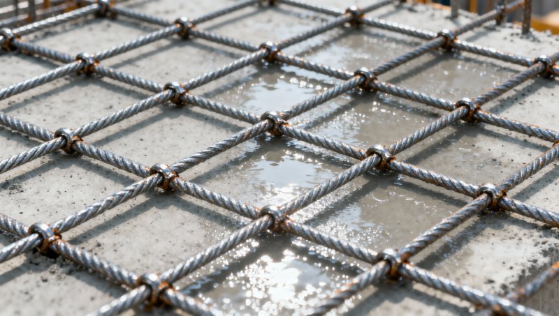
Mesh size (the center-to-center distance between parallel wires) governs how finely reinforcement is distributed across a concrete section. A 100 mm × 100 mm mesh doesn’t just mean “wires every 10 cm”—it defines the maximum probable crack width between adjacent bars under service loads. EN 1992-1-1 Annex G and ACI 318-19 both tie maximum crack spacing directly to bar spacing, assuming adequate bond and cover. But here’s what’s rarely stressed: reducing mesh size below 150 mm × 150 mm yields diminishing returns *unless* wire diameter and concrete cover are proportionally adjusted. Why? Because finer meshes increase surface area—and thus corrosion risk—if concrete quality or cover depth isn’t upgraded accordingly. In slabs exposed to de-icing salts or coastal environments, a 100 mm mesh with 6 mm wires may accelerate chloride ingress more than a 200 mm mesh with 8 mm wires—even if total steel area per m² is identical.
Wire Diameter: Where Strength Meets Ductility—and Bond
Wire diameter determines not only cross-sectional area but also anchorage performance. Thinner wires (e.g., 4.0 mm) provide higher surface-area-to-volume ratio, improving bond with concrete—but they also reduce local buckling resistance and strain capacity. Under flexural fatigue (think industrial floors or bridge decks), repeated micro-yielding at wire bends can initiate fatigue cracks earlier than expected—especially when yield strength exceeds 500 MPa and ductility drops below 12% elongation. That’s why ASTM A185 and EN 10080 specify minimum elongation requirements *by diameter class*: 5.0 mm wires must achieve ≥12% elongation; 6.0 mm wires, ≥10%. These aren’t arbitrary thresholds—they reflect the point where cold-drawing stress concentrations begin compromising post-yield energy absorption.
Yield Strength: The Trade-Off You Can’t Ignore
Higher yield strength (e.g., 550 MPa vs. 400 MPa) allows reduced steel area for the same moment capacity—but only if the design model accounts for reduced curvature ductility. Concrete’s tensile strain capacity is fixed (~0.0001); steel’s contribution to rotation capacity depends on how far it strains beyond yield before fracture. A 550 MPa mesh with 8% elongation delivers less plastic hinge rotation than a 400 MPa mesh with 18% elongation—even if both satisfy minimum area requirements. This matters most in seismic zones or structures subject to impact loading. GB/T 1499.3-2018 explicitly limits yield strength for welded mesh used in earthquake-resistant frames to ≤500 MPa unless verified ductility testing confirms ≥15% total elongation. No standard waives this—it’s physics, not paperwork.
Interdependence in Practice: When Compliance ≠ Performance
A common misstep is treating standards as checklists. For example, an EN 10080-compliant mesh labeled “B500B” meets minimum yield (≥500 MPa), tensile strength (≥550 MPa), and elongation (≥12%). But if that mesh uses 5.5 mm wires spaced at 200 mm × 200 mm in a 120 mm slab with 25 mm cover, its crack control performance may fall short of EN 1992-1-1’s serviceability limit states—not because it’s noncompliant, but because the *combination* of parameters creates insufficient restraint density for early-age shrinkage. Real-world validation shows such configurations increase probability of hairline cracking by ~35% in high-early-strength mixes (C40/50+), even with proper curing.
This interdependence is why OEM flexibility matters—not for customization’s sake, but to resolve conflicts between standard grades and project-specific demands. Consider a warehouse floor requiring high abrasion resistance (favoring 7 mm wires) but also rapid placement (favoring 150 mm × 150 mm spacing). Off-the-shelf B500B mesh rarely balances both; instead, a manufacturer capable of adjusting cold-drawing parameters while maintaining EN 10080 certification can deliver 6.5 mm wires at 150 mm spacing with 14% elongation—meeting both durability and constructability needs.
Where Carbon Steel Plate Fits In—And When It Doesn’t
While welded steel mesh dominates slab and wall reinforcement, carbon steel plate remains essential where localized bearing, stiffening, or connection integrity is critical—such as base plates for columns, bracket supports in precast connections, or shear keys in segmental bridges. Grades like Q235, A36, and S235JR offer balanced weldability, formability, and yield strength (235 MPa), making them suitable for fabrication-integrated reinforcement solutions. Their low carbon content (≤0.22%) ensures reliable fusion welding without preheat in most thicknesses up to 40 mm—a key advantage over higher-strength quenched-and-tempered plates when field welding is unavoidable. For applications demanding both plate-based anchorage and mesh-based distribution, coordination between plate thickness (e.g., 16–25 mm), edge detail geometry, and adjacent mesh wire diameter becomes a system-level design issue—not a component-level spec. Carbon Steel Plate Manufacturer solutions that maintain traceable mill test reports for both tensile and bend properties enable this integration without compromising QA continuity.
What to Verify Before Finalizing Specification
- Test report alignment: Confirm elongation values are reported *at the actual wire diameter used*, not extrapolated from tensile tests on larger rods.
- Bond verification: If using epoxy-coated or stainless-clad mesh, request pull-out test data per ASTM C234 or EN 10080 Annex B—not just adhesion strength, but bond-slip stiffness under sustained load.
- Weld integrity sampling: Demand macro-etch inspection of random weld joints—not just visual checks—to verify fusion depth and absence of micro-cracks, especially for meshes with wire diameters >6.0 mm.
- Environmental derating: In aggressive exposure classes (XC4, XS2), require minimum wire diameter ≥6.0 mm *and* confirm concrete cover complies with EN 206 Table 4.1N—not just national annex defaults.
There’s no universal “best” steel mesh for construction—only the right combination of mesh size, wire diameter, and yield strength for a defined structural action, exposure class, and construction sequence. The most efficient reinforcement isn’t the one with the highest MPa or smallest spacing. It’s the one whose parameters cohere—where geometry enables bond, strength enables ductility, and material behavior matches the concrete’s response envelope. That coherence starts not with catalog selection, but with questioning why each parameter value was chosen—and whether it holds up at the interface where steel meets concrete.
Please give us a message


Please enter what you want to find