Steel beam dimensions describe the shape of a beam’s cross-section: its overall depth, flange width, flange thickness and web thickness. These measurements affect how the beam carries bending and shear, how much space it occupies and how other components can connect to it. Two beams with similar depths can behave very differently if their flange and web proportions are different.
Dimensions are read alongside the section designation, material grade and applicable standard. A nominal size identifies a section, but the actual dimensions, tolerances and section properties come from the relevant published tables or approved product documentation.
Reading the Cross-Section
A typical I-shaped steel beam has two flanges connected by a web. The flanges form the upper and lower parts of the section when the beam is installed in its usual orientation; the web is the plate-like portion between them. The four dimensions most often used to describe this shape are shown below.
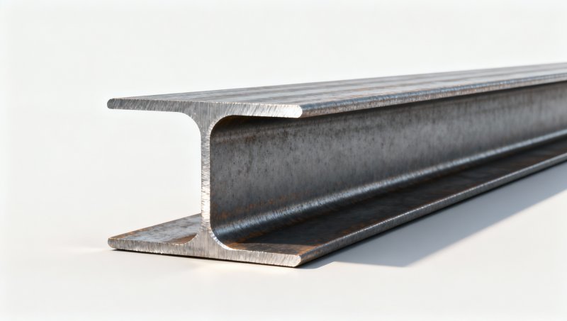
Symbols differ among standards and catalogues, so the accompanying drawing is often the clearest guide. Dimensions alone also do not capture every feature: rolled sections have rounded transitions, or fillets, where the web meets the flanges. Some section types have tapered flange faces, making the stated flange thickness a measurement at a specified location rather than at the edge.
Depth: The Outside Dimension That Influences Bending
Overall depth is measured from the top outside face to the bottom outside face. It is easy to confuse this with the clear distance between the flanges, which is smaller because it excludes their thicknesses. Fillets further reduce the flat web area available for a plate, bolt or weld near the flange junction.
For bending about the strong axis of a conventional I-section, placing flange material farther from the center generally increases bending stiffness and the section’s resistance to bending. That is why a deeper section can provide greater stiffness without a proportional increase in weight. The effect is not determined by depth alone: flange area, web dimensions and the complete cross-sectional geometry also matter.
Greater depth has physical consequences. A beam that fits structurally may leave insufficient room above a ceiling, below a floor or through an opening. Depth also affects the geometry of end connections and the space available for services passing around the beam. If the beam must fit into an existing frame, the actual depth and allowable tolerance matter more than a rounded nominal label.
A deeper beam is not automatically the right choice for every loading condition. Unsupported length, lateral restraint, connection details and the direction of bending all influence its performance. A structural design uses the relevant section properties and load conditions rather than selecting solely by depth.
Flange Width and Thickness
Flange width is the distance across the flange from one outer edge to the other. It affects the space available for bearing, welds and connection plates. It also contributes to resistance to bending about the weak axis, where the flange width is particularly important.
Width should not be treated as a direct measure of lateral stability. Wider flanges can contribute to stiffness, but lateral restraint, unbraced length and loading position still influence whether a beam is susceptible to lateral-torsional buckling. A section table and the structural design provide the basis for that assessment.
Flange thickness affects the area of material concentrated away from the center of the section. Thicker flanges can increase bending resistance, but they also add weight and alter connection details. For example, bolt grip length, edge access and welding preparation may need to accommodate a thicker flange.
When comparing shapes, confirm whether the flange surfaces are parallel or tapered. A caliper reading at the edge of a tapered flange may not match the tabulated thickness, even when the beam conforms to its specification. The standard’s measurement point resolves that apparent discrepancy.
Web Thickness and Clear Web Depth
The web joins the flanges and carries much of the vertical shear in a beam under ordinary vertical loading. Web thickness also affects local behavior near concentrated loads, supports and connections. A thin web may require closer assessment for buckling or local yielding; increasing overall beam depth does not eliminate that need.
The usable web height is smaller than the overall depth. For a parallel-flange section, subtracting the two flange thicknesses gives the distance between the inside flange faces, but the flat region is smaller still because of the fillet radii. This distinction matters when laying out bolt holes or fitting a connection plate. A plate sized to the full calculated inside depth may interfere with the curved transitions.
Web openings introduce another distinction. A hole that physically fits between the flanges is not necessarily structurally acceptable. Its size and location relative to supports, concentrated loads, other openings and connections require evaluation. Cutting an opening changes the local cross-section; the original tabulated properties no longer describe that location by themselves.
Nominal Size, Actual Dimensions and Weight
A beam designation is a shorthand for a standardized section, not a complete set of measurements. In one system, the designation may combine an approximate depth with mass per unit length; another may use a series name and nominal size. Units matter: a mass-per-length value and a weight-per-length value should not be compared as identical numbers without conversion.
Nominal depth can be rounded, and sections in the same nominal depth series can have different actual depths, flange dimensions and masses. Conversely, two beams with similar measured depths may belong to different section families. The designation must therefore be read together with the standard and its section table.
Mass per unit length is related to cross-sectional area and material density. It is useful for estimating handling and transport requirements, but it does not reveal how material is distributed. Two sections with similar mass can have different depths and flange proportions, producing different stiffness and strength about each axis.
The listed dimensions are nominal values subject to manufacturing tolerances. A measured variation is not automatically a defect, and an apparently close measurement does not by itself prove compliance. The relevant tolerance provisions, section type and measurement method establish what is acceptable.
From Dimensions to Section Properties
Beam tables translate cross-sectional geometry into properties used in structural calculations. These properties are related to depth, width and thickness, but they are not interchangeable with those dimensions.
- Cross-sectional area describes the amount of material in the section and is used with density to calculate mass per unit length.
- Second moment of area describes how area is distributed about an axis. Together with the material’s elastic modulus, it influences bending stiffness and deflection.
- Section modulus relates bending moment to elastic bending stress. Tables may also list a plastic section modulus for applicable strength calculations.
- Radius of gyration relates area distribution to cross-sectional area and is useful in stability calculations.
Each axis has its own properties. A beam installed with its web vertical has a strong axis and a weak axis; rotating the section changes which properties resist a given load direction. This is why a single depth value cannot establish bending capacity or deflection.
Material grade is separate from geometry. Two beams with the same dimensions can have different specified yield strengths. Conversely, a higher-strength grade does not necessarily make a beam noticeably stiffer under the same load: for beams with the same geometry, elastic deflection is governed by elastic modulus, loading and support conditions. Strength and stiffness are different design checks.
Measuring a Beam on Site or in a Workshop
Identify the section and its orientation first, then measure the overall depth and flange width across accessible outside faces. A straightedge can help bridge minor surface irregularities when measuring a large section. For thicknesses, use an appropriate caliper or thickness gauge and avoid taking the web reading through paint buildup, a weld or the flange fillet.
Record where each reading was taken. On a tapered flange, follow the measurement location specified for that section. For a web, measure on the flat portion away from the rounded junction. Surface coating, corrosion, mill scale and local damage can affect readings; note their presence rather than treating a single measurement as an exact representation of the original steel.
Length is a separate dimension from cross-sectional depth. For an installed beam, distinguish the physical cut length from the span between supports: the two can differ because of bearing lengths or connection arrangements. Similarly, the distance between flange tips does not describe sweep, camber or twist along the member, which require separate observations.
When Plate Dimensions Enter the Detail
Connection and stiffener plates are specified by their own thickness, width and length, then fitted to the beam’s actual geometry. Fillet clearance, bolt access and weld size affect the finished plate shape. A drawing that specifies only the beam designation may leave insufficient information to fabricate a plate that fits against the web.
Material should also be identified independently of shape. For example, 316L Stainless Steel Plate is a stainless steel plate material; its thickness and corrosion resistance do not establish the size, grade or load capacity of a structural beam. Where dissimilar materials meet, the connection detail and exposure conditions need separate consideration.
Comparing Sections Without Misreading the Numbers
Start with the complete designation and standard, then compare actual depth, flange width, flange and web thickness, mass per length and the relevant section properties. Keep the loading axis consistent throughout the comparison. A change that improves strong-axis bending performance may have a different effect on weak-axis behavior or available connection space.
For a replacement section, matching the original depth alone is insufficient. Flange width and thickness can affect bolted or welded connections, while a different web thickness changes the fit of web plates and may affect local resistance. Existing holes, bearing surfaces and clearances must also align with the proposed section.
For a new section, the drawing should make the intended beam series, size, grade and standard unambiguous. Where fit is tight, include the connection geometry and required clearances rather than relying on a nominal depth to communicate the available space.
Please give us a message


Please enter what you want to find