Thickness, flatness, and tolerance are often treated as line-item details on a stainless steel plate purchase order. In structural fabrication, they are assembly conditions. A plate can have the correct grade and nominal thickness yet still create fit-up problems, unstable weld preparation, distorted built-up members, or expensive machining and shimming during installation.
For project managers, the practical objective is straightforward: specify stainless steel plates that can move from receipt inspection into cutting, forming, welding, and final assembly without forcing the fabricator to compensate for avoidable dimensional variation. That requires more than selecting a thickness from a catalog. It requires matching the plate condition, tolerance standard, inspection method, and fabrication route to the structural function of the part.
Thicker material is not automatically safer, and a tighter tolerance is not automatically better. Both have value only when they address a defined design or fabrication risk. The right specification begins with understanding where variation can be absorbed and where it will accumulate.
Start with the fabricated part, not the nominal plate thickness
Nominal thickness is the design starting point, but the usable thickness is governed by the permitted negative tolerance. This distinction matters wherever the plate contributes directly to load capacity, connection geometry, corrosion allowance, or a machined final surface.
Consider a base plate, gusset, splice plate, stiffener, or support bracket. If its capacity calculation assumes the stated nominal thickness, the engineer must know whether the governing material standard permits a reduction below that nominal value. A plate ordered simply as “10 mm stainless steel” may be acceptable for a general cover or guard, while the same wording may be inadequate for a load-bearing component whose design leaves little margin.
The purchasing specification should therefore separate three questions:
- What minimum material thickness is required by the structural design?
- Which dimensional tolerance standard applies to the ordered plate?
- Does the supplied thickness, after allowed tolerance, still satisfy the design minimum?
This is especially important when a fabricator intends to machine a plate face, bevel a weld edge, countersink fasteners, or remove material during surface preparation. A nominal thickness that looks adequate before processing may become marginal after stock removal. Where this is relevant, the drawing should state the finished requirement and the allowance needed in the incoming plate.
Plate thickness also affects fabrication behavior. Thinner plates are more sensitive to heat distortion, local buckling, and handling damage. Heavier plates provide stiffness but can require higher forming force, more demanding weld procedures, and longer thermal cycles. In stainless steel, the cost impact of adding thickness can be significant, so adding material as a general precaution can be an inefficient substitute for a clear tolerance and fabrication plan.
Thickness selection should reflect the structural duty
For stainless steel plates used as architectural cladding supports, equipment enclosures, access platforms, or non-pressure guards, thickness selection often focuses on stiffness, dent resistance, and attachment details. For structural brackets, lifting frames, equipment supports, marine fabrications, and load-transferring connection plates, net section, bolt-hole geometry, weld capacity, and local bearing conditions carry more weight.
Project teams should avoid transferring thickness assumptions from carbon steel directly into stainless steel work. Stainless grades have different strength levels, thermal behavior, and fabrication considerations. The applicable design code, grade specification, and welding procedure must all support the selected plate thickness. A material grade name alone does not establish that the plate is suitable for a particular structural calculation.
Flatness becomes critical when plates must align, seal, or transfer load
Flatness is the condition most likely to be underestimated at procurement and most likely to cause trouble after cutting begins. A plate may be within thickness tolerance and still be unsuitable for a fabrication that depends on consistent contact between parts.
Flatness affects more than appearance. A bowed or locally wavy plate can change joint gaps, create uneven bearing at bolted interfaces, complicate automated cutting and drilling, and introduce residual stress when forced into alignment. If a plate is welded while restrained flat, the combination of incoming shape and welding shrinkage can increase distortion in the finished assembly.
Not every structural component needs a special flatness requirement. General brackets, small stiffeners, and parts that will be formed or heavily welded can often tolerate the standard delivery condition. Tighter flatness deserves attention when the plate will serve as a machined mounting face, sealing surface, sliding interface, precision base, laser-cut nest, long unbraced panel, or wide connection plate.
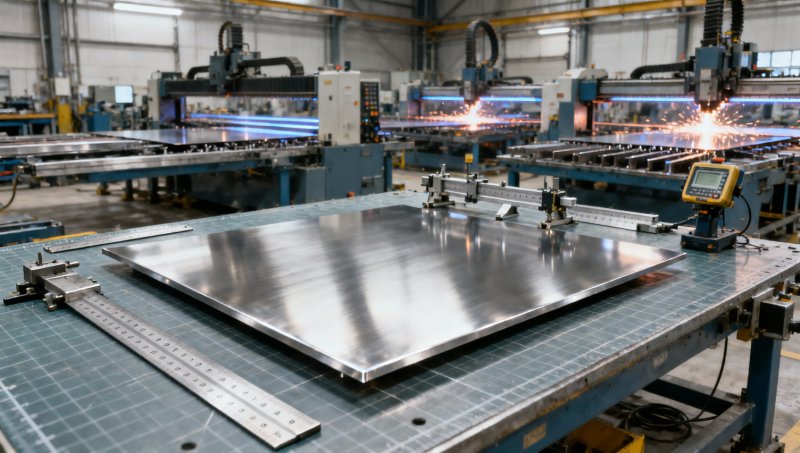
For these applications, “flat” should not remain an informal expectation. The order should identify the applicable flatness requirement, the reference standard where relevant, the inspection basis, and whether the plate will be evaluated before or after cutting. The inspection basis matters because a plate supported at several points can appear flat while showing a different result when measured on a stable reference surface.
Plate processing also changes flatness. Thermal cutting can introduce edge pull and local distortion. Cold forming creates residual stress. Welding adds shrinkage and angular movement. Mechanical straightening or leveling may improve incoming plate condition, but it does not eliminate the need to plan the sequence of cutting, fit-up, welding, and post-weld correction.
A useful procurement conversation is not “Can you supply flat plate?” It is: “What flatness is required at receipt, what process will be applied after receipt, and what final geometry is required on the fabricated part?” These are separate control points. Mixing them tends to produce disputes between designer, fabricator, and supplier once material has already been processed.
Tolerance must be specified where it changes fabrication outcomes
Dimensional tolerance includes thickness, width, length, squareness, edge condition, camber, and flatness. The required level depends on whether the plate is being used as raw stock or as a near-finished structural element.
Standard mill tolerances are often suitable when the fabricator will cut each part from oversized stock and has sufficient trim allowance. They are less suitable when plates are ordered close to finished dimensions, supplied for direct installation, or intended for repetitive assemblies where small deviations accumulate across multiple interfaces.
Width and length tolerances become important in large wall panels, tank components, machinery skids, façade support assemblies, and modular structures. A plate that is slightly oversize may seem harmless until it interferes with a predetermined gap, a nested assembly, or a transport frame. A plate that is undersize can be more serious when edge distance, overlap, or weld land has been assumed by the design.
Edge condition deserves the same attention. Mill edges, trimmed edges, cut edges, and sheared edges are not interchangeable for every application. If plates will be welded edge to edge, if a clean exposed line is required, or if the edge will form part of a sealing or bearing interface, the required condition should be stated. Leaving the edge requirement undefined can shift extra grinding, machining, or rework into the fabrication stage.
Where recognized ASTM, EN, JIS, or GB standards are named, the purchase order should identify the relevant edition and the precise tolerance category where the standard offers alternatives. Referencing only a material grade may establish chemistry and mechanical properties, but it may not define the dimensional condition expected by the project.
Flatness and grade selection should be considered together
Stainless steel is selected for corrosion resistance, appearance, hygiene, temperature performance, or service compatibility. Those reasons do not remove structural fabrication constraints. The grade, surface finish, plate thickness, and processing route interact.
Austenitic stainless steels, for example, can show pronounced thermal movement during welding and cutting compared with many carbon steel applications. A fabrication sequence that works well for a carbon steel frame may create more distortion in a stainless assembly if restraint, heat input, joint sequence, and cooling are not reviewed. The practical response is not to reject stainless steel plates for structural work; it is to make geometry control part of the fabrication plan from the start.
Surface finish can also affect what a project means by acceptable flatness. A plate intended for a visible architectural surface may require a different handling, lifting, and straightening approach than a concealed structural plate. Scratches, directional finish changes, and localized repair marks may be unacceptable even when the plate remains structurally sound.
Mixed-material structures introduce another check. Stainless plate components are sometimes incorporated into larger carbon steel systems for localized corrosion resistance or specific service requirements. The project should define isolation, joining methods, finish protection, and dimensional interfaces early. A flat stainless connection plate can still be difficult to install if the mating carbon steel frame has a different tolerance basis or has moved during welding.
The same principle applies when reviewing other steel components in a wider civil or industrial package. For example, a retaining structure may use carbon-steel Hot Rolled Steel Sheet Pile sections with interlocking profiles, while stainless steel plates are reserved for brackets, access components, splash-zone details, or equipment interfaces. Their functions, material grades, and dimensional controls differ. Treating all steel products as if they share the same plate flatness and tolerance expectations creates avoidable specification gaps.
Inspection should target the conditions that can stop fabrication
Incoming inspection is most effective when it focuses on the dimensions that would prevent the material from being used as intended. Measuring every characteristic on every plate may be unnecessary; accepting material only by mill certificate may be insufficient.
For critical stainless steel plates, a receiving plan can include verification of identification and traceability, grade documentation, actual thickness at representative locations, width and length, visible surface condition, edge condition, and flatness against the agreed requirement. The sampling method should be defined in proportion to the project risk, plate quantity, and consequences of replacement.
Traceability must remain intact through cutting when individual parts will be used in safety-sensitive, regulated, or highly corrosive service. A fabricator that separates all markings from the cut parts may later be unable to demonstrate which plate heat supplied a specific component. This is a process-control issue as much as a documentation issue.
For fabricated assemblies, distinguish material acceptance from final dimensional acceptance. A plate may pass receiving inspection but require a different check after forming, welding, machining, or pickling. Final inspection should measure the dimensions that affect installation and performance: interface flatness, hole location, overall alignment, weld preparation, and required clearances.
Questions to resolve before releasing the order
A concise technical review before purchase prevents most ambiguity. The project team should be able to answer the following questions clearly:
- Is the specified thickness nominal, minimum, or finished after machining?
- Which material and dimensional tolerance standards govern the plate?
- Which components require controlled flatness, and what measurement method will apply?
- Will thermal cutting, cold forming, or welding alter the incoming geometry beyond the final tolerance?
- Are plates ordered as raw stock with trim allowance, or close to finished size?
- Which dimensions must be verified at receipt, and which are checked after fabrication?
- Does traceability need to be retained for individual cut parts?
The most reliable stainless steel plate specification is usually not the one with the tightest limits. It is the one that states the limits that matter to the load path, assembly sequence, and final installation. When thickness, flatness, and tolerance are aligned with those conditions, the material arrives as a controlled fabrication input rather than a source of downstream correction.
Please give us a message


Please enter what you want to find