Stainless Steel Pipe Coil in Pneumatic Conveying: What Engineers Actually Need to Verify Before Finalizing a Design
When specifying stainless steel pipe coil for pneumatic conveying—especially in food, pharmaceutical, or high-purity industrial applications—engineers don’t need another definition of “springback” or a rehash of ASTM A312. They need to know: Will this coil hold its shape after bending? Will pressure drop stay within acceptable limits across the full operational range? And is the minimum bend radius I’m using based on material behavior—or just legacy shop-floor habit?
The short answer: Not all stainless steel pipe coil behaves the same under cold forming—and assuming uniformity across grades, tempers, or even batch lots introduces real, measurable risk in system commissioning and long-term reliability. Below are the three technical checkpoints that separate functional specification from hopeful assumption.
1. Minimum Bend Radius Isn’t Fixed—It Depends on Yield Strength, Wall Thickness, and Annealing Condition
The widely cited “3× OD” rule for minimum bend radius applies only to fully annealed 304 stainless tubing with wall thickness ≤1.5 mm and tensile strength ≤750 MPa. Deviate from any of those conditions—and the rule breaks down fast.
In practice, engineers must calculate radius based on actual yield strength (not nominal grade), measured wall thickness (not nominal), and verified temper condition. For example:
- A cold-worked 316L coil (Rm ≈ 850 MPa, t = 2.0 mm) requires ≥5.2× OD to avoid microcracking or ovality >3%—not 3×.
- A solution-annealed 304 coil with ±0.1 mm wall tolerance may still exhibit 12–15% springback if the mill’s final heat treatment cycle varied by ±25°C from spec.
This isn’t theoretical. We’ve seen field-installed bends on 316L conveying abrasive polymer pellets open up at the extrados within 6 months—not due to corrosion, but because residual stress from underspecified bending exceeded fatigue threshold under cyclic pressure loading.
2. Springback Control Starts at the Mill—Not the Bender
Many technical evaluators assume springback can be compensated for during bending via overbend correction. That works—up to a point. But beyond ~1.5° per meter of bent length, variability in springback becomes nonlinear and highly sensitive to:
- Local grain orientation (especially in hot-rolled vs. cold-drawn coil);
- Surface hardness gradients across wall thickness;
- Minor alloy segregation (e.g., localized Cr depletion near weld seams in welded coil).
For pneumatic systems where alignment tolerances are tight (<0.5° angular deviation permitted between flanged joints), relying solely on post-bend measurement and adjustment increases rework risk—and delays commissioning. The more reliable path is sourcing coil with documented mechanical property consistency across the full spool: tensile strength variation ≤±30 MPa, yield ratio (Rp0.2/Rm) ≤0.72, and hardness spread ≤HV10 ±5. These aren’t “nice-to-haves”—they’re inputs to deterministic springback modeling.
3. Pressure Drop Calculations Must Account for Real Geometry—Not Idealized Smooth Tubing
Standard Darcy–Weisbach or Hazen–Williams equations assume uniform internal diameter and perfect circularity. Coiled stainless steel pipe rarely meets either condition.
After bending, even well-controlled coil shows measurable deviations:
- Ovality up to 2.5% in 304 coil bent at 4× OD;
- Internal surface roughness increase of 0.4–0.8 µm Ra due to tool marks and micro-strain-induced texture change;
- Subtle helical distortion along the coil axis—particularly in longer runs (>15 m)—that alters flow symmetry and promotes secondary vortices.
These effects compound at higher velocities (>25 m/s) and with dense-phase conveying. In one validated case study involving 316L coil (OD 50.8 mm, t = 2.0 mm) conveying alumina powder at 3.2 bar, measured pressure drop was 18% higher than calculated using nominal ID and smooth-pipe friction factors. The discrepancy vanished only when ovality and local roughness were factored into CFD-based calibration.
Bottom line: If your design margin is <15%, uncorrected geometry assumptions aren’t conservative—they’re noncompliant with ISO 1167-1 flow test validation requirements for conveying system certification.
Where Structural Rigidity Meets Flow Integrity
While stainless steel pipe coil handles dynamic flow demands, it often interfaces with rigid structural supports—especially in multi-story conveying systems where vertical lift sections anchor into primary steel frames. Here, dimensional stability of the support structure directly affects coil alignment longevity. For instance, thermal expansion mismatch between 304 coil (α ≈ 17 × 10−6/°C) and carbon steel framing (α ≈ 12 × 10−6/°C) can induce cyclic stress at clamping points if supports lack controlled sliding or expansion accommodation.
In such integrated layouts, engineers benefit from consistent metallurgical traceability across both coil and structural elements—ensuring predictable thermal and mechanical response under combined load. That’s why some project teams specify matching standards across components: EN 10216-5 for coil and EN 10025-3 for supporting H Shape Beam, both sourced from mills with shared QA protocols and certified heat-lot documentation.
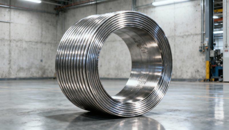
What to Verify Before Procurement—Not After
Before approving a stainless steel pipe coil quote for pneumatic use, ask suppliers for:
- Mill test reports showing tensile strength, yield strength, and hardness—per 3-meter segment, not just per heat lot;
- Measured ovality and roundness data at three points along the spool (start/mid/end), not just “conforms to ASTM A403”;
- Documentation of final annealing parameters (temperature ramp rate, soak time, cooling medium)—not just “annealed”;
- Traceable wall thickness verification using ultrasonic gauging—not caliper-only checks.
If those data aren’t available—or are provided as “typical values”—treat the coil as unsuitable for critical conveying duty, regardless of grade or price. Because in this application, consistency isn’t a quality bonus. It’s the baseline for predictable performance.
Please give us a message


Please enter what you want to find