For technical evaluators, understanding how i shaped steel beams transfer loads is essential to selecting safe, efficient structural solutions. Their geometry directly affects bending strength, stability, and material use in buildings and industrial frameworks. This article outlines the core load paths and design basics, helping you assess performance, specification fit, and manufacturing reliability with greater confidence.
What technical evaluators really need to confirm first
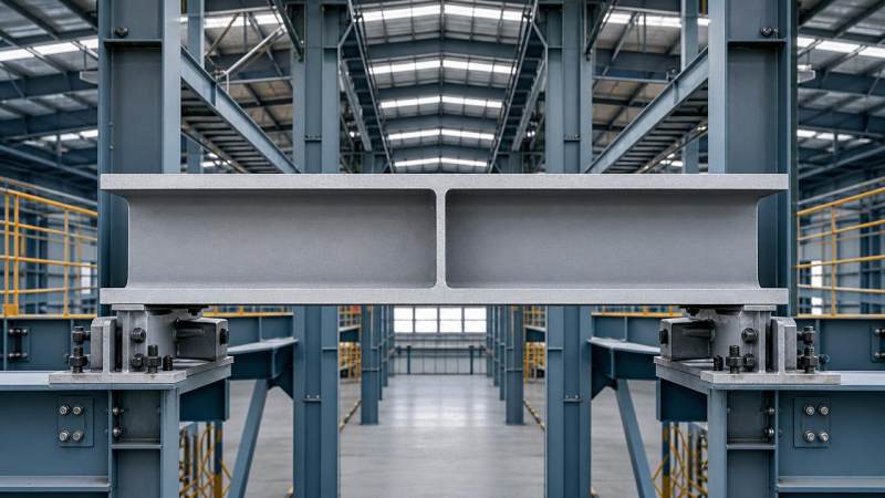
When engineers or procurement teams assess i shaped steel beams, the first question is not simply beam size. It is whether the section can carry the intended loads safely and predictably.
That means evaluating how loads move through the beam, how bending and shear are resisted, and how stability is maintained under real support and connection conditions.
For technical evaluators, the practical goal is clear: confirm that the selected beam section meets strength, serviceability, fabrication, and compliance requirements without unnecessary steel weight or sourcing risk.
In most projects, i shaped steel beams are chosen because they offer high bending efficiency. Material is concentrated in the flanges, where bending stresses are highest, while the web carries most shear.
This geometry makes the section economical for floors, platforms, industrial frames, warehouses, bridges, and equipment supports. But good performance depends on more than the shape alone.
Actual beam behavior also depends on span, support condition, load type, lateral restraint, connection design, steel grade, fabrication accuracy, and conformity to standards such as ASTM, EN, JIS, or GB.
How load paths work in i shaped steel beams
The term load path describes how gravity, live, equipment, or wind-related forces travel from the point of application through structural members and finally into columns, walls, foundations, and ground.
In a simply supported beam under downward loading, internal resistance develops mainly as bending moment and shear force. These internal actions are then distributed through different parts of the section.
The flanges resist most of the bending action. Under positive bending, the top flange is primarily in compression while the bottom flange is primarily in tension.
The web connects the flanges and transfers shear between them. It also contributes to bending resistance, though much less efficiently than the flanges because it lies closer to the neutral axis.
This is why the i shaped steel beams section is so effective. Steel is placed farther from the neutral axis, increasing the section modulus and moment of inertia without using excess material.
For evaluators, understanding this division of work matters. If a design is bending-controlled, flange size becomes especially important. If the beam is shear-critical, web depth and thickness deserve closer review.
Load paths also depend on where the load enters the beam. Uniformly distributed loads, point loads, eccentric loads, and concentrated reactions each create different internal stress patterns and local detailing needs.
For example, a heavy point load near midspan may govern flexural design, while a concentrated reaction near a support may increase web bearing and web crippling concerns.
Why section geometry matters more than many buyers assume
Technical comparisons should go beyond nominal beam depth. Two beams with similar overall height may behave very differently if flange width, flange thickness, web thickness, or root geometry are not comparable.
Section depth strongly influences bending stiffness and deflection. In many applications, serviceability limits control beam selection before ultimate strength becomes the governing criterion.
A deeper beam usually reduces deflection more effectively than simply increasing thickness. This can improve floor performance, equipment alignment, and user comfort in industrial and commercial structures.
Flange area and width affect moment capacity and lateral stability. Wider or thicker flanges can improve resistance, but they also change weight, welding demand, and connection details.
Web thickness affects shear capacity and local stability. Thin webs may be efficient, but they can become vulnerable to buckling, crippling, or fabrication distortion if not properly detailed.
Radius transitions and dimensional tolerances also matter in fabrication and fit-up. Reliable manufacturing control helps ensure that actual section properties match design assumptions during installation and service.
What basic design checks should be reviewed before approval
For a technical evaluator, beam approval should be based on several core checks rather than one headline capacity value. The most important are bending strength, shear strength, deflection, and stability.
Bending strength verifies that the beam can resist the maximum applied moment without exceeding the allowable or design limit state for the selected code framework.
Shear strength confirms that the web can carry the peak shear force, especially near supports or under concentrated loads. This becomes critical in short-span or heavily loaded members.
Deflection limits are often underestimated in sourcing discussions. A beam may satisfy strength requirements but still deflect too much for flooring systems, cladding supports, machinery bases, or crane-related structures.
Lateral-torsional buckling is another essential review item. When the compression flange is not adequately restrained, the beam can twist and buckle before reaching its theoretical bending capacity.
This is why unbraced length must always be considered. A beam that performs well in a braced frame may be unsuitable in an open-span arrangement with limited lateral support.
Local buckling checks are also important. Slender flanges or webs can lose effectiveness before the full section capacity is developed, depending on code classification rules.
Connection zone behavior should not be ignored. Welded seats, bolted end plates, stiffeners, and load introduction points can all affect whether the selected beam works as intended in the actual frame.
How support conditions change beam behavior
Support assumptions have a major effect on load distribution and design demand. A simply supported beam, continuous beam, and cantilever all produce different moment and deflection patterns under the same loading.
If the support detail in the field differs from the design model, the real structural response may shift. That can change peak moments, reactions, rotation demands, and even vibration behavior.
Technical evaluators should therefore confirm not only member size, but also how the beam is expected to connect to surrounding elements and whether those restraints are realistic.
For example, composite action with a slab may improve stiffness and capacity, but only if shear transfer and construction sequencing are properly accounted for in design.
Likewise, temporary erection stages can matter. A beam may be stable in the completed structure but vulnerable before full bracing or decking is installed.
Where material grade and manufacturing quality affect performance
Even a well-sized beam can become a project risk if material consistency or dimensional accuracy is poor. Technical evaluation should therefore include both section design and supplier capability.
Steel grade affects yield strength, ductility, weldability, and sometimes toughness. These properties influence not only resistance, but also fabrication methods and suitability for specific environments.
Manufacturing quality affects straightness, flange alignment, web centering, edge condition, and section tolerance. Variations in these factors can complicate erection or reduce confidence in structural behavior.
For international buyers, compliance with ASTM, EN, JIS, or GB standards is especially relevant. Documentation should clearly show grade, dimensions, tolerances, heat records, and inspection procedures.
Stable production capacity also matters from a risk perspective. Evaluators often need confidence that repeat orders will match the approved sample or project specification over time.
This is where an experienced structural steel manufacturer can add value, not only by supplying standard beam sections, but by supporting custom profiles, documentation, and specification matching for export projects.
Common mistakes when specifying i shaped steel beams
One common mistake is selecting based only on nominal size or weight per meter. Without checking section properties, unbraced length, and deflection criteria, this shortcut can lead to poor performance.
Another frequent issue is assuming that all international beam standards are directly interchangeable. Similar designations may still have meaningful differences in flange geometry, tolerance, or theoretical properties.
Evaluators should also avoid overlooking concentrated load effects. Local web reinforcement may be necessary even when overall bending and shear results look acceptable.
Corrosion protection assumptions should be reviewed early as well. Surface treatment, primer compatibility, and environmental category can influence lifecycle cost and maintenance demand.
Finally, do not separate beam evaluation from the wider system. The most efficient section on paper may create unnecessary complexity in transport, connections, or field installation.
How to compare suppliers beyond the beam datasheet
A credible technical review should ask whether the supplier can consistently produce the required section, certify it to the correct standard, and support project-specific processing if needed.
Questions worth asking include whether the supplier offers mill test certificates, dimensional inspection records, traceability, packing protection, and stable lead times for export delivery.
It is also helpful to confirm whether the manufacturer supports related steel products used in the same project package. This can simplify sourcing coordination and quality alignment.
For example, some projects that use structural beams also require wire products for mesh, fencing, barriers, or general industrial use. In those cases, sourcing consistency becomes a practical advantage.
An example is Mild Steel Wire Rod, available in Q195 and Q235 low carbon steel grades for applications such as wire mesh, packaging, fences, tie ropes, and general construction support.
With wire diameter options from 0.25 mm to 5.0 mm, tensile strength of 350 to 550 MPa, and good ductility, this type of supporting material can complement broader project procurement where steel compatibility matters.
A practical evaluation framework for specification fit
If you need to approve or compare i shaped steel beams, a structured checklist helps reduce ambiguity and speeds up technical decisions.
First, confirm loading conditions: dead load, live load, equipment load, dynamic effects, and any concentrated reactions. Then verify span, support assumptions, and required serviceability limits.
Second, compare section properties rather than labels alone. Review moment of inertia, section modulus, flange dimensions, web thickness, and section classification under the governing code.
Third, check stability conditions. Confirm the unbraced length, lateral restraint arrangement, and whether torsional effects or local buckling could reduce the nominal capacity.
Fourth, review fabrication and connection implications. Ask whether copes, holes, weld access, stiffeners, and transport limitations affect the feasibility of the proposed section.
Fifth, evaluate supplier reliability. Look for standard compliance, inspection discipline, production consistency, packaging quality, and export experience in your target market.
This approach helps technical evaluators move from general beam comparison to decision-ready assessment, balancing structural safety, manufacturability, and procurement control.
Conclusion
I shaped steel beams remain one of the most efficient structural forms because their geometry aligns material with the real demands of bending and shear.
For technical evaluators, the key is to understand not just what the section is called, but how loads travel through it, which checks govern performance, and where supplier quality affects reliability.
When bending, shear, deflection, stability, support conditions, and manufacturing consistency are reviewed together, specification decisions become clearer and project risk is reduced.
In short, good beam selection is not about choosing the heaviest option. It is about choosing the section that delivers verified performance, efficient material use, and dependable execution in the real structure.
Please give us a message


Please enter what you want to find