A welded H-section can leave the assembly fixture with flanges that are no longer parallel, a bowed web, or curvature along its length—even when the original plates were cut accurately. These changes can obstruct connection fit-up, alter bearing contact, and create extra straightening work. In 201 stainless steel h section manufacture, the main cause is uneven thermal expansion followed by weld shrinkage, not simply poor cutting accuracy.
The most effective control combines consistent joint fit-up, appropriately sized welds, balanced heat application, and a planned welding sequence. Restraint helps hold the geometry during fabrication, but it cannot eliminate shrinkage; excessive restraint may instead increase residual stress. Technical evaluation should therefore examine dimensions after cooling and fixture release, together with the qualified welding procedure and any subsequent correction.
Where the movement comes from
Grade 201 is an austenitic stainless steel. Compared with common carbon structural steels, austenitic stainless steels generally have higher thermal expansion and lower thermal conductivity. Heat remains more concentrated near the weld, while the hot region tries to expand against cooler surrounding material. Local plastic deformation develops when these incompatible movements exceed the material’s ability to respond elastically.
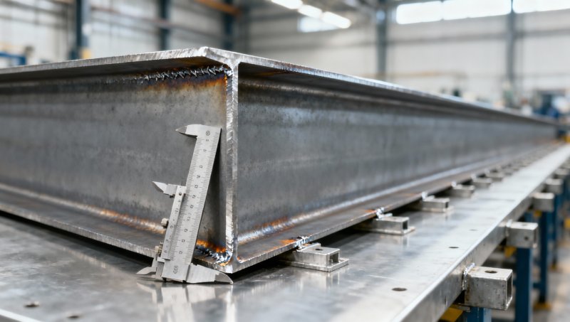
During cooling, the weld metal and heated base material contract. Because this contraction is neither uniform across the section nor symmetrical through every plate thickness, it produces several distinct movements. An H-section is especially sensitive because long web-to-flange welds connect relatively wide plates to a narrower central web.
These symptoms may occur together. A section with both flange rotation and twist should not be treated as a simple straightness problem: correcting longitudinal curvature alone may leave the connection surfaces misaligned.
Separate welding distortion from incoming geometry errors
Before adjusting welding parameters, establish whether the assembly was straight and square before welding. Plate camber, residual stresses released during cutting, uneven flange widths, and an off-centre web can all produce apparent “welding distortion.” A fixture may temporarily conceal those errors.
Measure plate flatness and edge straightness before assembly, then record flange spacing, web position, and squareness after tacking. Use consistent measurement stations along the member so that pre-weld and post-weld readings can be compared. For long members, the support arrangement must also be repeatable; self-weight deflection can otherwise be mistaken for permanent curvature.
Joint gaps deserve particular attention. A varying web-to-flange gap changes the weld volume needed to achieve the specified joint geometry. Filling a large gap usually requires more deposited metal and may require additional passes, increasing local shrinkage. Pulling the gap closed with clamps can store elastic strain that becomes visible only after release.
Tack welds should hold the intended alignment without forcing inaccurate components into place. Their size, spacing, placement, and treatment during final welding belong in the fabrication procedure. Cracked or defective tacks must be addressed before incorporation into the finished joint.
Heat input: reduce excess, not fusion quality
Higher arc energy per unit length generally heats a larger region and increases the potential for distortion. However, reducing energy without checking joint fusion is not a sound solution. A visually straight H-section with incomplete fusion is not an acceptable trade-off.
For a conventional arc process, arc energy per unit length is estimated from voltage multiplied by current, divided by travel speed, using consistent units. Estimating heat transferred to the workpiece also requires an appropriate process efficiency factor. With pulsed welding, recorded average power or the method required by the applicable procedure standard is preferable to calculations based on peak current alone.
The useful production controls are practical:
- Specify the required weld size rather than allowing operators to add metal “for strength.” Oversized fillets increase shrinkage without automatically improving the designed connection.
- Keep travel speed and deposited cross-section consistent along the joint. Local slowdowns can create distortion concentrations.
- Use pass sizes that the qualified procedure can reliably fuse. Numerous passes can add reheating cycles, while an excessively large pass may create a wider heated zone.
- Control interpass temperature and measure it at the location defined by the procedure. Accumulated heat can defeat an otherwise balanced sequence.
GMAW, GTAW, and other suitable processes can produce acceptable joints when properly qualified, but the process name alone does not predict dimensional accuracy. Mechanized welding may improve repeatability, yet it will repeatedly reproduce poor fit-up or an unbalanced sequence unless those inputs are corrected.
Grade 201 should not automatically inherit a procedure developed for grade 304 or for carbon steel. Confirm the actual material specification, delivery condition, filler selection, shielding requirements, and procedure qualification coverage. Distortion control is only one part of joint acceptance; cracking resistance, mechanical properties, and service-related corrosion requirements remain relevant.
Arrange the sequence around shrinkage balance
A built-up H-section normally has longitudinal joints on both sides of the web at each flange. Completing one long weld before addressing the opposing joints can pull the assembly progressively out of alignment. The resulting deformation may become difficult to recover through later welds.
A better sequence distributes contraction around the section. Depending on access and equipment, this can involve alternating opposing welds, progressing in matched lengths, or using coordinated welding arrangements. “Balanced” does not necessarily mean welding every joint simultaneously: simultaneous arcs can increase total heat accumulation, so temperature control still matters.
Segmented welding needs a defined plan
Back-step and skip sequences can help distribute heat and limit cumulative movement. In back-step welding, short runs proceed opposite to the overall direction of progress. In skip welding, separated portions are welded before the intervening lengths are completed. Neither method changes a design requirement for a continuous weld into permission to leave unwelded gaps.
Short runs also create more starts and stops, which require suitable overlap, crater treatment, and inspection. Their distortion benefit must therefore be weighed against production time and defect risk. For a repetitive section, a representative fabrication trial is more useful than choosing a sequence solely because it worked on a different plate thickness.
The trial should reproduce the intended section geometry, joint preparation, welding position, supports, and fixture release method. Record dimensional movement at defined stages rather than measuring only the final corrected component. This identifies whether the largest change occurs during one weld group, during cooling, or when restraint is removed.
Use restraint without hiding the final shape
Clamps, strongbacks, and assembly fixtures resist movement while the welds cool. They can reduce visible distortion, but restraining thermal contraction creates stresses in the assembly. Once clamps are released, elastic springback may reveal curvature that was not apparent during welding.
Fixtures should locate the web and flanges consistently, support the member against sag, and permit a controlled release sequence. Contact surfaces and tooling used on stainless steel should also be managed to avoid carbon-steel contamination. Restraint spacing must suit plate stiffness: widely spaced clamps may hold the ends while allowing local flange rotation or web buckling between them.
Presetting can be useful where repeated trials establish a predictable movement. The assembly is positioned slightly opposite to the expected distortion so that shrinkage brings it toward the required shape. A preset derived from one thickness or weld size should not be transferred unchanged to another section. Excessive preset can introduce poor fit-up and increase the welding needed to close joints.
Final acceptance measurements should be taken after adequate cooling, complete fixture release, and any approved correction. Also distinguish dimensional conformity from residual stress: a straight section can still contain substantial welding stresses.
Correction methods have limits
Mechanical straightening may correct curvature or flange angle, but correction must account for local strain, section stability, and surface damage. Grade 201 work-hardens, so repeated bending can change local properties and make further correction more difficult. Press loads should be applied through suitable supports rather than concentrated against an unsupported web.
Thermal straightening requires a controlled, approved method. Applying uncontrolled heat with a torch can create additional distortion and affect surface condition or corrosion performance. A generic carbon-steel heating practice is not sufficient justification for use on a 201 stainless assembly.
Where dimensional error is recurring, changing the fabrication process is preferable to relying on repeated correction. Investigate weld volume, gaps, sequence, and fixture behaviour before increasing straightening effort. Correction records should identify the method and include reinspection of affected dimensions and any weld regions subjected to significant deformation.
Make the acceptance requirements specific to the section
A technical enquiry should define flange width and thickness, web depth and thickness, section length, weld configuration, and the required dimensional limits. Include straightness, twist, flange angularity, web position, and local flatness where they affect assembly. A single percentage tolerance cannot adequately describe all these characteristics.
Product documentation must also remain separated by material and manufacturing route. For example, the listed Rail product covers carbon-steel and medium-manganese-steel options, with a stated ±1% tolerance. That tolerance is not a dimensional acceptance basis for a welded 201 stainless H-section, and its material grades do not establish stainless welding procedure coverage.
For the H-section itself, agree which current material, welding qualification, execution, and inspection standards apply to the contract. General structural welding documents do not all cover stainless steel or every application. Quality-management certification likewise does not demonstrate qualification of a particular weld procedure.
The manufacturing submission should connect the welding procedure to the actual production arrangement: weld size and passes, operating ranges, sequence, interpass control, tack practice, restraint, and correction limits. Inspection records should distinguish incoming geometry, post-weld dimensions, and final dimensions after release or straightening. Non-destructive testing assesses weld discontinuities; dimensional inspection assesses shape. Neither substitutes for the other.
For slender webs, heavily restrained assemblies, or demanding fatigue service, dimensional compliance alone may be insufficient. The design assessment may need to consider welding residual stress and geometric imperfections. The decisive supplier evidence is therefore a repeatable route to the specified free-state geometry, supported by qualified welding and traceable inspection—not merely a photograph of a straight member held in a fixture.
Please give us a message


Please enter what you want to find