A 200 mm I-beam does not have one fixed weight per meter. The 200 mm dimension identifies its nominal overall depth, but flange width, web thickness, flange thickness, and corner geometry determine its cross-sectional area. For a parallel-flange section, a useful first estimate is mass per meter = [2btf + (h − 2tf)tw] × 0.00785, with all dimensions entered in millimeters and the result expressed in kg/m.
That equation treats the section as three rectangles. It is suitable for preliminary checks, but a rolled I-beam also contains root fillets and may have tapered flanges or rounded edges. For a specified standard section, the published sectional area and mass per meter should take precedence over an estimate based on simplified geometry.
Identify the dimensions behind the “200 mm” designation
Before calculating 200mm i beam weight per meter, establish whether “200” is an actual measured depth or part of a nominal section designation. A beam family may contain several sections with similar depths but substantially different flange dimensions and masses. Sections from different national standards are not interchangeable merely because their nominal depth is the same.
The rectangular calculation requires four dimensions:
For a symmetric section, both flanges have the same width and thickness. If they differ, calculate their areas separately. Also distinguish overall depth from clear web height: using the full 200 mm depth for the web while counting both complete flanges would count the web–flange intersections twice.
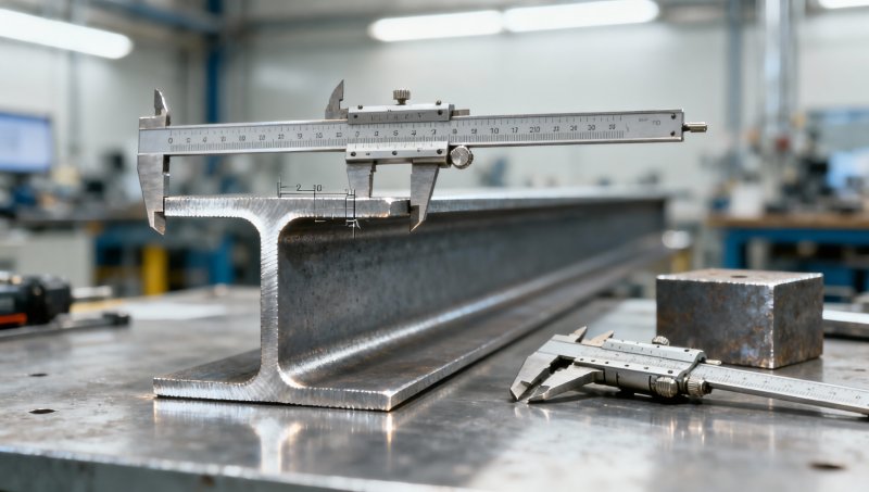
A dimensioned cross-section should show the root radius, flange slope, and edge radii where relevant. These features explain why a section-table value can differ from the result obtained using only the four principal dimensions.
Convert cross-sectional area into mass per meter
The calculation follows a direct volume-to-mass relationship:
m′ = ρA
Here, m′ is mass per unit length in kg/m, ρ is density in kg/m³, and A is area in m². For conventional theoretical calculations of structural steel, a density of 7,850 kg/m³ is commonly used. Where a specification requires another density, that specified value governs.
Since 1 mm² equals 10−6 m²:
m′ (kg/m) = A (mm²) × 0.00785
If the sectional area is listed in cm², the equivalent expression is:
m′ (kg/m) = A (cm²) × 0.785
For a symmetric, parallel-flange I-section without fillet corrections, the two flanges contribute 2btf. The web contributes (h − 2tf)tw. Therefore:
Arect = 2btf + (h − 2tf)tw
This is a theoretical geometric calculation, not a measurement of delivered material. Density conventions, rolling tolerances, surface coatings, and actual lengths can all affect the relationship between calculated mass and weighed mass.
A worked calculation for a 200 mm parallel-flange section
Consider an illustrative section with the following dimensions. These dimensions demonstrate the method; they do not identify a particular standardized beam.
- Overall depth, h = 200 mm
- Flange width, b = 100 mm
- Web thickness, tw = 5.5 mm
- Flange thickness, tf = 8 mm
The combined flange area is:
Aflanges = 2 × 100 × 8 = 1,600 mm²
The clear web height is 200 − 2 × 8 = 184 mm, giving:
Aweb = 184 × 5.5 = 1,012 mm²
The rectangular sectional area and theoretical mass are consequently:
Arect = 1,600 + 1,012 = 2,612 mm²
m′rect = 2,612 × 0.00785 = 20.50 kg/m
For a 6 m length, this gives approximately 123.0 kg before any geometry correction. Keep the unrounded mass per meter in the calculation and round the final result, especially when extending quantities across many lengths.
The significance of flange and web dimensions becomes clear when comparing other hypothetical 200 mm-deep sections:
All three have the same overall depth, yet their calculated masses differ markedly. A weight comparison based only on “200 mm beam” therefore lacks enough information to establish equivalence.
Account for root fillets without overstating precision
Hot-rolled sections have curved transitions between the web and flanges. In a simplified parallel-flange model, these root fillets add material outside the three rectangular areas already counted.
If each transition is an ideal quarter-circle fillet of radius r, the additional area at one corner is the area of a square minus a quarter circle:
Aone fillet = r² − πr²/4
For four identical root fillets:
Afillets = (4 − π)r²
Using an illustrative root radius of 9 mm for the worked example:
Afillets = (4 − π) × 9² ≈ 69.53 mm²
A ≈ 2,612 + 69.53 = 2,681.53 mm²
m′ ≈ 2,681.53 × 0.00785 = 21.05 kg/m
The correction adds approximately 0.55 kg/m, or 2.7% relative to the rectangular estimate. This percentage belongs only to the stated geometry; it is not a general correction factor for all I-beams.
The expression also assumes ideal right-angle transitions and neglects material removed by rounded flange edges. A manufacturer’s actual nominal profile may use geometry that is not represented exactly by this construction. Use a documented profile drawing, a properly defined CAD section, or the applicable section table when these differences matter.
Tapered flanges require a different area treatment
For a tapered-flange I-beam, flange thickness changes across the width. Substituting the maximum thickness near the web into 2btf overestimates flange area; substituting the thinner tip thickness underestimates it.
The governing relationship is the area under the thickness profile:
Aflange = ∫ t(x) dx
For a flange region with a truly linear taper between thicknesses t1 and t2, its area equals its width multiplied by the average thickness:
Aregion = width × (t1 + t2)/2
However, an entire rolled flange is not necessarily one simple trapezoid. The web junction, root fillet, flange slope, and toe rounding must be represented consistently. A thickness shown in a standard drawing may be defined at a particular location rather than as an average thickness.
The safest manual approach is to divide the profile into non-overlapping rectangles, trapezoids, and curved regions. Alternatively, calculate the area from a closed CAD outline constructed from the specified dimensions. Do not combine an average flange thickness with a web height derived from a different thickness reference; that can introduce gaps or overlapping areas.
Check the result against the correct section standard
A calculated mass becomes useful only when it is tied to an unambiguous section identity. Relevant references include EN 10365 for dimensions and masses of specified hot-rolled channel, I, and H sections; JIS G 3192 for dimensions, mass, and permissible variations of hot-rolled steel sections; and GB/T 706 for hot-rolled section steel. ASTM A6/A6M provides general requirements, including dimensional information and tolerances, for covered rolled structural steel products.
These references are not interchangeable catalogs. Confirm the section family, full designation, applicable edition, and dimensional requirements for the order. Under the European system, dimensional tolerances also depend on the section type: EN 10034 addresses structural steel I and H sections, while EN 10024 addresses hot-rolled taper-flange I sections.
A steel grade alone does not identify beam geometry. Specifying a material grade such as ASTM A36 does not establish flange width, thickness, sectional area, or mass per meter.
When a supplier’s mass differs from a hand calculation, compare the inputs before treating the difference as an error:
- Does the designation refer to the same section series and nominal dimensions?
- Are the flanges parallel or tapered?
- Does the published area include root fillets and edge rounding?
- Is the quoted figure theoretical mass, measured mass, or a shipping quantity including other material?
- Are both calculations using the same density and units?
A small difference can result from geometry or rounding. A large difference warrants checking section identity and units before investigating material density.
Use the calculated value within its proper limits
Dimensional errors propagate directly into mass estimates. For the rectangular model, increasing web thickness by 1 mm adds (h − 2tf) mm² of area. In the worked example, that equals 184 mm², or approximately 1.44 kg/m. Increasing both flange thicknesses by 1 mm, while holding overall depth constant, adds 2(b − tw) mm², approximately 1.48 kg/m for the same example.
These sensitivities explain why thickness measurement matters. Measure flat regions rather than fillets, remove interfering surface contamination where appropriate, and compare measured dimensions with the specified tolerance rules. An isolated measurement is not necessarily representative of an entire delivered length or batch.
For structural self-weight, convert mass into force. A beam at 21.05 kg/m produces a gravity load of approximately:
w = 21.05 × 9.81 / 1,000 ≈ 0.207 kN/m
Mass per meter does not establish bending resistance, stiffness, or buckling performance. Those checks require section properties, material strength, restraint conditions, and the applicable design rules. Two beams of similar mass can distribute their steel differently and have different structural behavior.
For quantity calculations, multiply the accepted mass per meter by the actual specified lengths and quantities. Coatings, end plates, stiffeners, and other attachments require separate allowances when estimating fabricated or shipped mass. Where settlement is based on weighing rather than theoretical mass, the contractual measurement basis remains decisive.
A defensible 200 mm I-beam calculation therefore starts with complete dimensions, uses a consistent geometric model, and ends with a check against the identified section standard. The rectangular formula gives a transparent estimate; the documented sectional area establishes the nominal value for a standard rolled profile.
Please give us a message


Please enter what you want to find