How span affects a 12-inch I-beam load capacity chart
A 12 inch i beam load capacity chart is only useful when its span and design assumptions match your project. As the unsupported span increases, bending demand and deflection rise, often reducing the allowable load even when the beam section remains unchanged. Nominal depth alone is not enough: section properties, steel grade, load distribution, support conditions, and lateral restraint all influence the result. Understanding those relationships helps separate a useful preliminary comparison from a misleading capacity claim.
The practical question is not simply, “How much can a 12-inch beam carry?” It is, “Which exact section can carry this load over this span, with these supports and restraints, under the governing design standard?” A chart can help answer that question, but only after its assumptions have been checked.
A 12-inch depth does not identify the beam
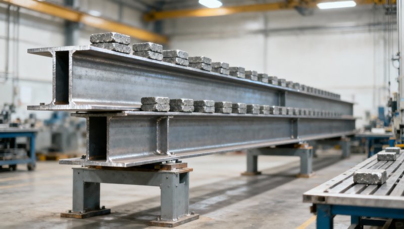
“12-inch I-beam” is a broad description rather than a complete structural designation. It may refer to an American wide-flange section, a tapered-flange beam, or a metric section described approximately in inches. Sections with similar depths can have substantially different flange widths, web thicknesses, weights, and bending properties.
For an American W12 section, the full designation includes nominal depth and weight per foot. Actual depth varies by section. Two W12 beams therefore do not share one universal load capacity. For metric sections, use the exact designation and dimensional table rather than treating a roughly 300 mm depth as an equivalent structural product.
The properties most relevant to a span comparison include major-axis moment of inertia, elastic and plastic section modulus, shear properties, and lateral-torsional buckling properties. The specified steel grade establishes strength requirements; the section geometry establishes how effectively that material resists bending and deformation.
Why longer spans reduce chart capacities
Consider a simply supported beam carrying a uniformly distributed load. Under elementary elastic beam theory, the maximum bending moment and midspan deflection are:
M = wL2/8
δ = 5wL4/(384EI)
Here, w is load per unit length, L is the design span, E is the elastic modulus, and I is the second moment of area about the bending axis. Use consistent units throughout. These equations assume simple supports, constant stiffness, small deflections, and bending about the intended axis; they are not universal formulas for every installation.
The squared and fourth-power terms explain why span changes deserve attention. If the same beam carries the same distributed load intensity over a span that is 25% longer, bending moment becomes about 1.56 times as large, while elastic deflection becomes about 2.44 times as large. Those are mathematical ratios, not published ratings for a particular 12-inch section.
If available bending resistance remains constant, the bending-limited distributed load varies inversely with L2. When deflection is limited to a span ratio such as L/360, the deflection-limited distributed load varies inversely with L3. For a fixed absolute deflection limit, it varies inversely with L4.
A span comparison should distinguish distributed load intensity from total load. Total uniformly distributed load is W = wL. Consequently, a reduction in pounds per foot is not the same proportional reduction in total pounds supported.
These relationships are useful for checking whether chart values look plausible. They cannot replace calculations where lateral stability, shear, local buckling, or connection behavior controls.
Strength and serviceability can give different answers
A beam may have adequate strength and still deflect too much for its intended use. Floors, equipment platforms, roof framing, and members supporting brittle finishes can have different serviceability requirements. L/360 is a familiar example, not a universal acceptance limit. The relevant criterion may apply to live-load deflection, total-load deflection, or movement after sensitive finishes are installed.
Increasing steel yield strength can improve some strength checks, but it does not proportionally increase stiffness. Structural steel grades generally have similar elastic moduli. If deflection controls, a section with greater moment of inertia, a shorter span, or a revised support arrangement may be more effective than a higher-strength grade.
Strength calculations also depend on design format. An allowable-strength-design chart and a load-and-resistance-factor-design calculation do not use loads and resistances in the same way. A value described as “allowable load” should not be compared directly with a factored load without confirming the chart’s basis.
AISC 360 provides a recognized framework for structural steel strength design in US practice, while EN 1993 provides the Eurocode framework for steel structures. Applicable editions, load standards, national provisions, and project specifications must be confirmed. A material specification such as ASTM A992 does not itself provide a beam load-capacity chart.
Span and unbraced length are not interchangeable
The span used for beam analysis is the distance defined by the structural support model. It is not necessarily the delivered steel length or the clear opening between support faces. Bearing geometry and the governing design convention need to be resolved before selecting a chart row.
Unbraced length concerns restraint against lateral movement and twist. A beam spanning between two columns may have intermediate lateral restraints without having intermediate vertical supports. Those restraints can improve lateral-torsional buckling resistance, but they do not shorten the vertical bending span.
This distinction can change the result significantly. A chart assuming adequate compression-flange restraint may overstate the capacity of an otherwise identical beam installed without effective bracing. Decking or secondary members should not automatically be counted as restraint: their connections, stiffness, strength, and load path must be adequate.
Installation conditions also matter. A beam that is restrained in the completed structure may be unrestrained while being erected or before decking is secured. That temporary condition needs its own assessment.
Load position and supports change the calculation
A uniformly distributed load chart cannot be reused unchanged for equipment feet, a hoist, or a concentrated reaction from another beam. For a central point load P on a simply supported beam, maximum moment is PL/4 and midspan deflection is PL3/(48EI). The load distribution therefore changes both demand and the way capacity varies with span.
Concentrated loads also require local checks at load and support locations. Web yielding, web crippling, bearing details, and connection resistance may govern even when overall bending appears acceptable. Loads applied away from the shear center can introduce torsion that a basic major-axis chart does not address.
Continuous beams and cantilevers need different models. Assuming fixed supports merely because a beam is welded into place is especially risky: the connection and supporting structure must provide the rotational restraint assumed in the analysis. Moving loads, impact, vibration, and fatigue can require checks beyond a static capacity table.
How to screen a chart before comparing quotations
Read the notes before the load values. A useful 12 inch i beam load capacity chart should make enough information available to establish the following:
- The exact section designation, steel grade, and bending orientation.
- The span definition, support model, and assumed lateral restraint.
- Whether loads are distributed or concentrated, and whether values are force, force per length, or pressure.
- Whether beam self-weight is included or must be deducted from the stated capacity.
- The design method, governing standard, and deflection criterion.
- Whether the values represent strength, serviceability, or the lower of several limits.
If loading is given as pressure, convert it using the appropriate tributary width before comparing it with a line-load table. Include permanent attachments and supported construction where required. Avoid interpolating across widely spaced spans when the governing failure mode may change between entries; a direct calculation is more defensible.
Carry the engineering assumptions into the supply documents
For overseas sourcing, a nominal size match is not enough. The purchase specification should connect the approved calculation to the supplied section: designation, dimensions, grade, length, tolerances, testing documentation, and any fabrication details affecting performance. Substituting a similar-depth section requires an engineering review, not just a dimensional comparison.
Hongteng Fengda is a China-based structural steel manufacturer and exporter supplying beams, angles, channels, cold-formed profiles, and customized components. For projects using ASTM, EN, JIS, or GB specifications, the useful sourcing discussion is which exact product standard and grade apply, what inspection records are required, and whether cutting, drilling, or welding details match the approved design. These requirements should be settled before production and delivery dates are finalized.
Material identity deserves the same discipline for associated components. The listing titled 316L Stainless Square steel rod includes supplied information identifying model and material as 201 stainless steel. That discrepancy needs clarification before specifying the product. Square-bar properties cannot be transferred to an I-beam capacity calculation, and the grade should be confirmed through the agreed specification and material documentation rather than inferred from a listing title.
Before releasing a beam order, have the responsible structural engineer confirm the selected section against the actual span, load arrangement, restraint, and serviceability requirements. Then ensure the quotation and inspection documents identify that same section and grade. The chart is a screening tool; the project-specific calculation and verified supply specification determine whether the beam is suitable.
Please give us a message


Please enter what you want to find