Holes reduce the net section of a steel angle by removing steel from a potential tensile fracture path. For an angle with holes, the basic calculation starts with the gross cross-sectional area and subtracts the hole deductions along that path. However, the smallest net section may follow a staggered route through several holes, and an angle connected through only one leg may require a further allowance for shear lag.
This creates three separate questions: how much steel remains, how effectively the connection engages that steel, and which failure mode controls the design. Counting every hole in the connection and subtracting them from the gross area will not answer these questions correctly.
Gross area, net area, and effective net area serve different purposes
The gross area, Ag, is the cross-sectional area before hole deductions. For a rolled angle, use the area listed for the specified section or calculated from its actual geometry. Simply multiplying each leg width by the thickness and adding the results counts the corner overlap twice; ignoring the root geometry can also introduce a discrepancy.
The net area, An, is the area remaining along a selected fracture path after the required hole deductions and any permitted stagger adjustments. It describes the geometry of that section, rather than the total volume of steel removed by drilling or punching.
The effective net area, Ae, accounts for how the tensile force reaches the remaining section. In the AISC approach, where applicable:
Ae = U × An
Here, U is the shear-lag factor. When only one leg is bolted to a gusset plate, the outstanding leg receives force indirectly through the connected leg and angle heel. Stress therefore does not develop uniformly across the entire section near the connection.
These areas correspond to different design checks. Gross-section yielding depends on gross area and yield strength. Net-section rupture depends on net or effective net area and tensile strength, using the applicable design standard. A hole deduction should not simply be applied to every resistance calculation.
Calculate the deduction at a section, not across the whole bolt group
For a straight section perpendicular to the tensile force, passing through round holes in material of uniform thickness, the basic expression is:
An = Ag − Σ(dded × t)
In this expression, t is the steel thickness and dded is the hole dimension used for the net-area deduction under the governing standard. The summation includes only the holes intersected by that particular section.
Consider an angle with several bolts arranged in one longitudinal row. A transverse cut through one bolt position generally intersects one hole, even though the connection contains several holes along its length. Subtracting every hole in that row would treat separate cross sections as if they were one section.
If two holes lie side by side across the developed section at the same longitudinal position, a straight cut can intersect both. Both deductions then belong in that calculation. The distinction is between holes distributed along the member and holes intercepted across the same potential fracture path.
The bolt diameter is not automatically the hole deduction. Bolt clearance, oversized holes, slots, and the standard’s prescribed deduction allowance can all affect the calculation. The drawing should identify the hole size and type separately from the bolt designation.
For slotted holes, orientation matters. Establish the dimension intercepted by the candidate section and apply the relevant standard’s treatment. Using a round-hole assumption for every slot can misrepresent the remaining ligament.
Why a staggered fracture path can govern
A fracture can follow a zigzag route between holes at different longitudinal positions. Such a path may intercept more holes than a straight transverse cut, but the longitudinal separation provides a stagger credit in the net-area calculation.
For uniform-thickness material, the familiar stagger expression used in the AISC approach is:
An = Ag − Σ(dded × t) + Σ[(s2 / 4g) × t]
Here, s is the longitudinal spacing between successive holes on the path, measured parallel to the force. The transverse spacing, g, is measured perpendicular to the force. Each permitted diagonal transition contributes its own stagger term.
The positive term does not mean that staggering restores the material removed by a hole. It is a geometric allowance for the longer route between offset holes. A zigzag path still requires a deduction for every hole it crosses.
For a simple comparison, a straight path crossing one hole has a deduction of ddedt. A competing path crossing two equal holes has a deduction of 2ddedt, reduced by the applicable stagger credit. The two-hole path governs when its resulting net area is smaller. Counting holes alone cannot identify the critical path.
Sketch the plausible straight and staggered routes before calculating them. Include paths through holes on either leg where the layout permits, and compare the resulting areas. This makes the calculation traceable and helps prevent a visually obvious transverse section from becoming the only section checked.
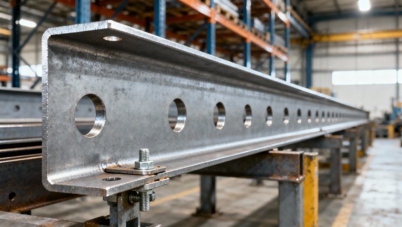
Holes on opposite legs need an angle-specific spacing treatment
A steel angle is a folded section. When a candidate path crosses holes on both legs, their transverse separation must be evaluated using the developed-section convention required by the design standard. A direct spatial measurement between hole centers does not represent that distance.
In the AISC treatment for holes in opposite legs, the transverse gage is the sum of the gages measured from the backs of the angle, less the angle thickness. Using a different reference point without converting the dimensions can produce an incorrect stagger credit.
The calculation sketch should therefore show the load direction, longitudinal spacing, hole gages, thickness, and selected path. A flat developed view is useful, provided its dimensions preserve the standard’s angle geometry convention.
Connecting one leg changes how much net area is effective
A single-angle brace is often bolted to a gusset through one leg. The outstanding leg contributes steel area, but force must spread into it over the connection length. This is the physical reason for shear lag.
Two angles can have the same gross area, hole deductions, and net area yet have different effective tensile resistance because their connections engage the section differently. Connection length, bolt arrangement, section geometry, and the position of the connection relative to the angle centroid can affect the applicable shear-lag treatment.
A longer connection can improve force distribution under applicable provisions, but adding a bolt does not automatically produce a particular improvement. The connection must fit the conditions of the selected equation or tabulated factor.
Where a standard permits an expression such as U = 1 − x̄/L, x̄ represents the relevant eccentricity and L the connection length as defined by that provision. This expression should not replace an angle-specific rule when that rule governs the arrangement.
Shear lag also does not cover every consequence of eccentric loading. A connection through one leg can introduce bending, and the member or connection may need additional checks. Treating the angle as a uniformly stressed strip can miss these effects.
A satisfactory net section does not establish connection capacity
Net-section rupture is one possible limit state. A bolted angle connection can also be controlled by bolt resistance, bearing at the holes, tear-out near an edge, block shear, or the gusset plate.
Block shear follows a different path from a full transverse net-section fracture. It involves a block of material bounded by shear paths along the connection and a tension path across its end. Bolt-group length, end distance, and edge distance influence this mechanism.
This explains why preserving a large net area does not necessarily make a connection adequate. Holes placed close to an end may leave enough steel across the angle while providing insufficient resistance along a tear-out or block-shear path.
Increasing thickness can improve several resistances, but it does not correct every layout problem. Moving a bolt line, increasing an end distance, changing the connection length, or engaging both legs may address the controlling mechanism more directly. Each change also affects fabrication access and gusset detailing.
Use one design framework consistently
The governing structural standard determines hole deductions, stagger rules, shear-lag treatment, and resistance factors. AISC and Eurocode approaches should not be treated as interchangeable collections of equations.
In particular, Eurocode provisions for angles connected by one leg include connection-specific treatment. Importing an AISC shear-lag factor into a Eurocode resistance expression can change the intended calibration of the check.
A material specification serves another purpose: it establishes requirements for the steel product. An angle supplied to an ASTM, EN, JIS, or GB material specification still needs a connection design under the project’s structural standard. The material certificate provides strength and grade information; it does not establish the capacity of the finished hole pattern.
For custom angle components supplied by Hongteng Fengda, the purchase specification should therefore connect the steel grade, section dimensions, and fabrication drawing to the project’s design basis. A general reference to international standards is less useful than identifying which requirements apply to each part of the supply.
Fabrication details that can change the assessment
The design calculation should describe the fabricated angle. Hole tolerances, thickness tolerances, and permitted fabrication methods belong in the drawing or technical specification so that production and inspection use the same assumptions.
- Hole size and shape: identify standard, oversized, or slotted holes and their orientation.
- Hole coordinates: define gages, longitudinal spacing, stagger, end distances, and edge distances from clear reference points.
- Steel thickness: distinguish the nominal section designation from the thickness basis required for design and acceptance.
- Hole condition: inspect for cracks, damaged edges, excessive burrs, and unauthorized enlargement.
- Drawing changes: reassess field-drilled holes and connection revisions before accepting them as equivalent to the approved layout.
A burr does not replace load-bearing material removed by a hole. Cracking or damage around a hole can also create a condition that a clean geometric deduction does not capture. Likewise, an unused hole still reduces any potential fracture section that crosses it.
For galvanized angles, the zinc coating provides corrosion protection but is not counted as structural steel thickness. Hole edges and coating continuity deserve attention, particularly where drilling or cutting occurs after galvanizing.
If the component is formed from Galvanized Steel Coil Sheet, establish the substrate grade, steel thickness, bend geometry, and applicable cold-formed design provisions. The coating designation describes a protection characteristic; tensile capacity comes from the steel substrate and the finished member geometry.
The most useful review record is a drawing with candidate fracture paths marked beside the area calculations, followed by the applicable effective-area and connection checks. That record shows whether the selected angle has enough remaining steel, whether the connection develops it effectively, and whether another failure mechanism controls before net-section rupture occurs.
Please give us a message


Please enter what you want to find