A frame can appear adequately sized on a drawing yet behave very differently once it carries roof loads, equipment, wind pressure, or repeated vehicle impacts. The reason is often not the nominal steel weight alone, but the relationship between steel tubing dimensions and the way forces travel through the frame.
For technical evaluators, outside diameter or overall section depth, wall thickness, corner geometry, unsupported length, and material grade must be considered together. A larger tube is not automatically the better choice, and a heavier wall is not always the most efficient one. The correct section depends on whether the member is governed by axial compression, bending, torsion, local buckling, connection strength, serviceability limits, or a combination of these conditions.
This discussion focuses on structural hollow sections used in welded frames, machinery bases, modular buildings, racks, agricultural structures, equipment supports, and industrial fabrication. It also explains why accurate dimensional specification matters when sourcing tubing or custom cold-formed structural components to ASTM, EN, JIS, GB, or project-specific requirements.
Load capacity is not one number
When someone asks how much load a steel tube can carry, the technically correct answer is: it depends on the loading mode and the frame geometry. A vertical post under centered compression is assessed differently from a beam carrying a distributed roof load. A diagonal brace sees tension and compression cycles. A rectangular tube used as a cantilever may be controlled by deflection long before it reaches its nominal yield strength.
In practical frame design, the most important checks usually include:
- Axial capacity: resistance to direct tension or compression.
- Flexural capacity: resistance to bending moment.
- Shear capacity: resistance to transverse loading near supports or concentrated loads.
- Buckling resistance: stability under compression, including global and local buckling.
- Deflection and vibration: serviceability performance under working loads.
- Connection capacity: the ability of welded, bolted, or gusseted joints to transfer the applied forces.
A tube can be strong enough in pure material terms but still be unsuitable because it buckles at a long unbraced length, deflects too much, has insufficient wall thickness for a connection, or cannot tolerate the local forces introduced by a bolt, base plate, or weld.
Outside dimensions determine stiffness more dramatically than many buyers expect
The external size of a tube—its outside diameter for circular hollow section (CHS), or its width and depth for square and rectangular hollow section (SHS and RHS)—has a major influence on bending stiffness. This is because steel farther from the section’s centerline contributes disproportionately to the second moment of area, commonly called the moment of inertia, I.
For a beam, deflection is closely related to the ratio of span and stiffness. In simplified terms, higher EI means lower deflection, where E is the elastic modulus of steel and I is the section’s moment of inertia. Since structural steels have broadly similar elastic modulus regardless of grade, changing the tube geometry is usually the most direct way to improve stiffness.
Consider two rectangular tubes with similar steel area. The deeper section generally performs much better when bending occurs about its strong axis. Moving material away from the neutral axis creates a larger section modulus, Z, which improves bending resistance. This is why an RHS oriented with its deeper side vertical can carry far more gravity-induced bending than the same RHS turned 90 degrees.
That orientation decision is easy to overlook in procurement documents. A specification that gives only “100 × 50 × 4 mm RHS” without identifying member orientation, loading plane, and connection arrangement may leave fabrication teams with unnecessary ambiguity.
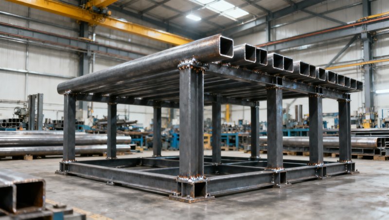
Wall thickness affects more than section weight
Wall thickness is often treated as a simple capacity upgrade: increase thickness, gain strength. While that is true to a degree, thickness has several separate effects that deserve to be evaluated individually.
Thicker walls increase cross-sectional area, which improves nominal axial tension and compression capacity. They also increase the section modulus and moment of inertia, although a modest increase in outside dimension may deliver a larger stiffness benefit than an equivalent increase in wall thickness. Where bending and deflection govern, enlarging the profile can therefore be more material-efficient than merely selecting a much heavier gauge.
Thickness is especially important where local behavior controls. Thin-walled tubing can experience local plate buckling in the flat faces of an RHS or SHS before the steel reaches its expected yield stress. The relevant concern is the width-to-thickness ratio of the wall elements. A wide, thin face is more susceptible to wrinkling or inward buckling under compression; a more compact wall proportion provides more reliable plastic or elastic performance under code design rules.
Connection design also makes wall thickness critical. A tube wall that is adequate along the member span may be too thin at a bolted connection, where bearing, tear-out, punching, or localized wall deformation becomes a concern. Welding onto thin tubing requires equally careful control. Excessive heat input can distort the section, while concentrated welds can introduce local stresses that are not reflected in a basic beam calculation.
Compression members: length can outweigh section size
Columns, struts, and compression braces reveal why steel tubing dimensions cannot be selected in isolation. A short tube may carry a high compressive force based largely on its cross-sectional area and yield strength. As the unsupported length grows, global buckling becomes more influential.
The governing parameter is often expressed through slenderness, which relates effective buckling length to the radius of gyration, r. Larger tube dimensions generally increase r, making the member less slender and more stable. But the effective length is equally important. End restraint, bracing points, frame sway, and joint stiffness can change the buckling condition substantially.
A common procurement mistake is to compare only wall thicknesses: for example, choosing a heavier 80 mm square tube instead of checking whether a 100 mm square tube with a more suitable wall may provide superior buckling resistance at similar or lower mass. The latter often places more steel farther from the centroid, increasing the radius of gyration and improving compression efficiency.
For compression members, evaluators should confirm whether the design uses the actual clear member length, a code-defined effective length factor, and the weaker-axis properties of the selected section. Square and circular tubes behave more uniformly in different directions than rectangular tubes, but RHS members can be highly efficient when their stronger axis is aligned with the principal load direction and lateral restraint is properly provided.
Section shape changes how the frame behaves
Round, square, and rectangular tubing are not interchangeable merely because their nominal area or mass is similar. Each shape has a different balance of fabrication practicality, torsional behavior, directional stiffness, and connection accessibility.
For frames exposed to torsion—such as offset equipment supports, sign structures, cantilevered assemblies, and irregularly loaded machine frames—closed steel tubing offers an important benefit over open sections. Its enclosed shape provides much greater torsional stiffness. Still, torsional demand should not be assumed away: eccentric connections, uneven load paths, and welded attachments can create twisting even in apparently straightforward frames.
Steel grade raises strength, but does not solve a stiffness problem
Higher-strength steel can increase the design resistance of a tube where yielding governs. This may permit a reduction in wall thickness or a higher load rating for the same geometry, subject to the applicable design standard. However, grade selection does not materially change the elastic modulus of steel. A higher-yield tube will not automatically deflect less under service load.
This distinction matters in structures with strict alignment, cladding, glazing, conveyor, or equipment tolerances. If the concern is excessive sag, vibration, or frame drift, the solution may be a larger outside dimension, a shorter span, additional bracing, or a revised load path—not simply a higher-grade material.
Material documentation should identify the relevant standard, grade, chemical composition limits where required, mechanical properties, and dimensional tolerances. For internationally sourced structural tubing and fabricated components, the project team should also verify whether the specified standard addresses the product form being supplied. ASTM, EN, JIS, and GB requirements are not automatically interchangeable without engineering review.
The nominal dimension is only the beginning
Design calculations typically use nominal or specified section properties, but fabrication quality depends on actual dimensions staying within permitted tolerances. Outside width, depth, diameter, wall thickness, corner radius, straightness, twist, and length can all affect fit-up and performance.
Wall thickness is particularly sensitive in hollow sections because even a small reduction affects area, local slenderness, weld behavior, and connection bearing. Technical purchasers should define whether inspection is based on nominal thickness, minimum permissible thickness, or a specific tolerance standard. They should also establish where thickness measurements will be taken, especially for cold-formed profiles whose corner geometry differs from the flat wall regions.
For welded frames, straightness and squareness are not merely cosmetic concerns. Initial imperfections can increase second-order effects in compression members and create assembly problems at bolted interfaces. A well-designed frame deserves equally disciplined dimensional control during cutting, forming, welding, and final inspection.
Connections can become the weak link
A tube’s calculated member capacity has limited value if the joint cannot transfer the load. Frame connections introduce concentrated stresses that are often more severe than the stresses in the member’s midspan. A thin tube wall may flatten beneath a bolt group; an end plate can produce local yielding; a branch member welded onto a chord may require reinforcement or a detailed tubular-joint assessment.
Before finalizing steel tubing dimensions, technical evaluators should ask practical questions: Is there enough internal access for bolts or backing? Will the wall support the required fillet or groove weld? Does the base plate distribute column load adequately? Are stiffeners needed near high-load connections? Can the proposed geometry be fabricated repeatedly without distortion?
These questions are especially relevant for OEM structural steel components. A supplier may be able to manufacture the requested profile, but manufacturability review can identify changes that preserve design intent while reducing weld difficulty, handling risk, or unnecessary material use.
A disciplined selection sequence for structural frames
Rather than selecting a tube from a weight table and working backward, start with the member’s role in the frame. Identify the governing load combinations, load direction, span or effective length, support conditions, bracing arrangement, and connection layout. Then compare candidate sections based on section area, moment of inertia, section modulus, radius of gyration, wall slenderness, and available connection capacity.
Check ultimate limit states and serviceability separately. A member that passes strength design may still be unsuitable if it deflects excessively, transmits vibration, or creates unacceptable movement at equipment interfaces. Where corrosion allowance, galvanizing, coatings, or long-term environmental exposure matter, these should be incorporated into the specification rather than left as a late purchasing adjustment.
For global projects, clear documentation reduces the risk of receiving tubing that is visually similar but mechanically unsuitable. A complete request should state profile size, wall thickness, grade, governing product standard, length tolerance, surface condition, testing or inspection requirements, and whether the supply scope includes cutting, drilling, welding, assembly, or protective treatment.
Making steel tubing dimensions work for the whole frame
The most economical tube is rarely the lightest section on paper or the thickest wall available. It is the section that meets strength, stability, stiffness, connection, fabrication, and sourcing requirements as a coordinated system. Increasing outside dimensions may be the most efficient response to bending or buckling. Increasing wall thickness may be essential for local buckling resistance and durable connections. Changing from RHS to SHS or CHS may improve behavior under multidirectional or torsional loading.
When evaluating structural steel tubing, treat the dimensions as design variables rather than catalog labels. Review them alongside member length, orientation, steel grade, joint detailing, and applicable standards. This approach gives project teams a clearer basis for technical approval and helps manufacturers translate engineering intent into consistent, buildable structural steel components.
Please give us a message


Please enter what you want to find