Connection eccentricity can make an angle brace carry bending as well as axial force. A member that appears adequate when checked only for tension or compression may develop higher local stresses, reduced compression resistance, or a connection failure when the actual load path is considered. The effect is especially relevant to single angles attached through one leg, where the connection force generally does not pass through the section’s centroid.
For technical evaluation, eccentricity deserves attention whenever the proposed detail differs from the assumptions behind the member calculation. Its significance depends on the force direction, connection length, angle orientation, restraint, and whether the brace carries tension, compression, or reversing loads. Some design standards provide specific methods for qualifying angle configurations, but those methods have limits. An axial-only check is defensible only when the applicable provisions and the physical detail support it.
Locate the load path before assessing the section
The first task is to establish where force enters the angle and how it reaches the supporting structure. For a single angle bolted through one leg, the bolt line is displaced from the centroid of the full cross-section. A welded connection can also introduce eccentricity: weld placement, effective weld lengths, and the stiffness of the connected parts determine how force is transferred.
At a section where an axial force acts with an offset, the corresponding first-order moment can be expressed as M = N × e, where N is the force and e is the perpendicular distance between its line of action and the relevant centroidal axis. This relationship explains why changing the connection geometry can change demand without changing the brace force.
However, the moment calculated at the connection should not automatically be applied as a uniform moment along the entire brace. The member’s end restraint, deformation, connection flexibility, and framing geometry influence the bending distribution. A useful analysis distinguishes the local force transfer at the attachment from the response of the brace over its unsupported length.
Angle geometry adds another complication. The principal axes are rotated relative to the legs, so an eccentric force may cause bending about both principal axes. Calculating stress using one convenient leg axis and a single section modulus can miss the critical corner. Where torsion or coupled instability is relevant, the shear-center location and torsional restraint also require attention.
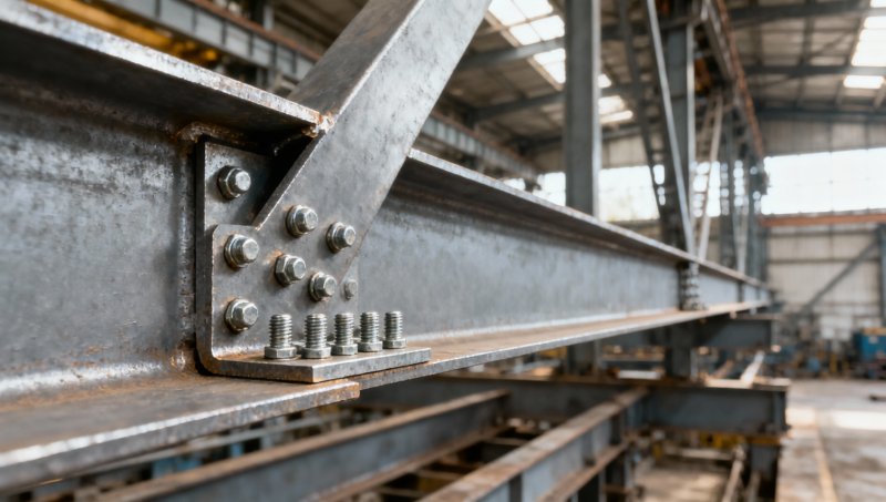
A connection sketch should identify the angle centroid, bolt or weld arrangement, gusset plane, brace work line, and any offset to the supporting member. Two different eccentricities may be present: the attachment may be offset from the angle centroid, and the brace work line may miss the intended framing intersection. Correcting one does not necessarily resolve the other.
Equal-leg angles do not eliminate this problem. Their geometry is symmetric about one principal axis, but a connection through only one leg still introduces an asymmetric load path. Likewise, a gusset aligned with the structural work point does not establish that the angle itself is loaded concentrically.
Tension and compression respond differently
In tension, distinguish bending from incomplete force transfer
A tension angle connected through one leg transfers force into the attached leg before the outstanding leg becomes fully engaged. This uneven stress distribution is associated with shear lag. Depending on the governing standard and connection arrangement, the tensile rupture calculation may use an effective net area that accounts for incomplete participation of the cross-section.
Shear lag and eccentric bending are related to the connection geometry, but they represent different effects. A shear-lag factor used in a tensile resistance calculation should not be treated as a universal allowance for every bending effect. Conversely, an explicit bending calculation should not automatically replace the effective-area requirements of the applicable tension-member provisions.
The evaluator should examine gross-section yielding, net-section rupture, and connection resistance using a consistent design basis. Bolt holes reduce the net area, while the connected leg’s edge distances and bolt arrangement influence block shear, bearing, and tear-out. Welded details avoid bolt-hole deductions but still require checks of force transfer through the weld group and adjacent base metal.
A longer connection can improve force distribution and, under applicable provisions, increase effective tensile participation. Yet adding bolts has consequences beyond connection length. It changes the hole pattern, potential failure paths, and distribution of force within the group. The revised detail needs a complete check rather than an assumption that additional fasteners always increase usable brace capacity.
For a brace intended to act only in tension, confirm how compression is accommodated when loading changes direction. If the structural analysis allows the member to become inactive, the resulting load redistribution must be represented. A tension-only assumption cannot be carried into a system that depends on the same brace for compression resistance.
In compression, eccentricity interacts with instability
Compression makes connection eccentricity more consequential because bending can increase as the member deflects. The initial offset creates a moment; lateral displacement under compression can produce additional moment through second-order effects. The importance of that amplification depends on slenderness, restraint, and the applied compression relative to the member’s resistance.
Single angles can be sensitive to flexural buckling and, where relevant, flexural-torsional buckling. The outstanding leg, asymmetric attachment, and rotational flexibility at the ends affect the instability response. An assessment based only on gross area and a nominal yield strength therefore gives little assurance of compression performance.
Some standards contain special compression-member provisions for single angles that incorporate connection eccentricity through prescribed slenderness or resistance procedures. These are useful when the arrangement satisfies their conditions. The evaluator must check the required connection details, end conditions, and loading assumptions before using them. A formula developed for a particular angle configuration should not be extended to a different configuration without justification.
Where those provisions do not apply, the analysis may need to represent axial force, bending, and second-order response explicitly. The model should use credible restraint and connection stiffness. Assuming fully fixed ends because a gusset looks substantial can overstate resistance; assuming ideal pins can also omit moments transmitted by the actual detail.
For angle steel bracing and components subject to repeated load reversal, the assessment extends beyond a static resistance check. Connection slip, local yielding, brace buckling, and subsequent deformation can influence cyclic behavior. Seismic applications require the relevant system-specific detailing and capacity-design provisions in addition to ordinary member and connection checks.
The connection can govern before the angle reaches its resistance
Increasing angle thickness or selecting a higher-strength steel may improve member resistance while leaving the load-transfer problem unresolved. An eccentric connection must transmit the associated moments as well as the axial force. Depending on the geometry, those moments can produce additional fastener shear, fastener tension, plate bending, or a combination of actions.
The direction of the offset matters. Eccentricity within the gusset plane creates a different demand from an offset through its thickness. Bolt-group calculations should follow the actual force and moment components rather than assume equal force in every bolt. Where plate separation or deformation introduces prying action, that behavior also needs consideration.
For welded angles, the effective weld-group geometry determines resistance to the applied force and moment. Equal weld lengths along two edges do not necessarily position the weld-group resultant at the angle centroid. An arrangement intended to balance force transfer must be evaluated using its effective weld lengths, locations, and compatible deformation.
The gusset is part of this load path. Its unsupported dimensions, thickness, attachment to the frame, and freedom to bend affect how the brace end behaves. Depending on the arrangement, relevant checks include yielding, rupture, block shear, compression buckling, and out-of-plane bending. A satisfactory angle-member calculation does not establish that the gusset can deliver the required force to the frame.
The same reasoning applies where a brace connects to a channel collector or support bracket. A Channel Steel Supplier may provide the channel section for that assembly, but its suitability depends on the web and flange geometry, attachment position, and torsional restraint. An offset brace connection can introduce local bending or twist into the channel, so the receiving component must be checked as part of the assembly.
Clearances can create further offsets. Packing plates, single-sided attachments, and fabrication changes may move the load-transfer plane from the position assumed in design. These details should appear on the connection drawings, especially where relatively small geometric changes alter fastener demand or out-of-plane behavior.
Choose a detail that reduces the governing effect
Several connection changes can reduce eccentricity, but each addresses a different part of the problem. Moving the bolt line within the connected leg may reduce the distance to the centroid, subject to edge-distance, spacing, and fabrication requirements. Extending the connection may improve tensile force distribution. Changing the gusset position may reduce an offset in the assembly. None of these adjustments automatically solves all three issues.
Connecting both legs can improve force transfer when the supporting geometry permits it. The detail must still provide a compatible load path through both attachments; unequal stiffness can prevent the force from dividing as assumed. Access for bolting or welding, inspection, and the resulting restraint also affect whether this is a practical solution.
Paired angles placed on opposite sides of a gusset can reduce the assembly’s overall eccentricity when they are arranged and connected symmetrically. Each angle still requires an appropriate member check, and the connections between components must justify any built-up-member behavior assumed in analysis. Two angles should not be assigned composite properties solely because they share end gussets.
Using a larger single angle can be appropriate where section resistance governs. It is less effective when the dominant problem is an offset load path, a flexible gusset, or inadequate fastener geometry. Compare proposed revisions against the governing limit state: the most useful change is the one that reduces the controlling demand or increases the relevant resistance.
Make the calculation and fabrication drawing agree
A technical review should begin with a small set of explicit inputs: the brace force envelope, including reversal where applicable; the angle size and orientation; the unsupported length and restraint; and the complete connection geometry at both ends. The calculation should then identify which eccentricities are represented directly and which are addressed by a permitted standard-specific method.
In an AISC-based design, the relevant framework includes tension-member, compression-member, combined-force, and connection provisions. In a Eurocode-based design, the corresponding member and joint rules must be used with the applicable national choices and project requirements. Effective-area expressions, resistance factors, and connection assumptions should remain within one consistent framework. Material compliance with ASTM, EN, JIS, or GB alone does not demonstrate compliance of the completed brace connection.
The fabrication documents should make the consequential dimensions unambiguous: connected leg, bolt gauge, hole arrangement, weld locations and effective lengths, gusset orientation, packing, and support attachment. Steel grade and section tolerances should match the calculation inputs. Substituting an unequal-leg angle, reversing its orientation, or altering the connection pattern can change the eccentricity even when the nominal area appears similar.
The decisive review question is whether the manufactured assembly delivers force through the path assumed in the resistance checks. When that path is clear, the evaluator can determine whether a standard angle-specific method is applicable, whether combined axial and bending analysis is needed, or whether revising the connection geometry offers a more effective solution than increasing the steel section.
Please give us a message


Please enter what you want to find