How Steel Sheet Pile technical specifications affect driving resistance in dense clay soils
Driving steel sheet piles into dense clay soils is rarely a matter of brute force—it’s a precise interaction between pile geometry, material behavior, and soil rheology. For project managers overseeing deep foundation or retaining wall installations in low-permeability, high-cohesion strata, excessive driving resistance doesn’t just delay schedules; it risks pile buckling, interlock failure, or refusal before design depth is reached. The root cause is often not poor hammer selection or inadequate pre-boring—but subtle mismatches between *steel sheet pile technical specifications* and the geotechnical reality.
Dense clays—particularly overconsolidated, stiff to very stiff clays with undrained shear strengths (su) exceeding 100 kPa—exhibit time-dependent strength recovery (thixotropy) and low hydraulic conductivity. This means soil displacement during driving isn’t instantaneous or fully recoverable. Resistance builds rapidly not only from static end-bearing and shaft friction but also from pore pressure buildup, which temporarily increases effective stress around the pile flange and interlock zone. Under these conditions, minor variations in section geometry or wall thickness can shift the balance between drivability and structural safety.
Section geometry governs both penetration efficiency and lateral load transfer. A narrow, deep web—common in Larssen-type sections like AZ or Z profiles—reduces frontal area and initial toe resistance, easing entry into dense clay. But if the flange width is too narrow relative to web depth, lateral stability during driving suffers: the pile may tilt or “walk” laterally under eccentric hammer impact, increasing localized soil compression and resistance. Conversely, wider flanges improve alignment control but raise total surface area and drag—especially problematic where clay adhesion (skin friction coefficient α > 0.7) dominates shaft resistance. Project managers must verify that the chosen section’s moment of inertia (Iy) and section modulus (Wy) aren’t optimized solely for bending capacity post-installation, but also evaluated against driving-induced bending moments during toe penetration through stiff layers.
Wall thickness directly affects both stiffness and energy absorption. In dense clay, driving resistance rises nonlinearly with depth—not linearly—and peak resistance often occurs just below the top of a stiff layer. A pile with insufficient wall thickness may flex excessively at the point of maximum soil reaction, causing local buckling in the web or flange. This doesn’t always result in visible damage, but it redistributes stress into the interlock, accelerating wear or galling. Thicker walls (e.g., 12–16 mm vs. 8–10 mm for standard 600-mm-wide sections) reduce deflection under hammer blow, maintain interlock integrity across multiple drives, and lower the risk of “locking up” due to interlock deformation. However, increased mass also raises required hammer energy—so thickness must be balanced against available equipment capacity and site constraints.
Material grade influences drivability more than commonly assumed. ASTM A572 Gr. 50 or EN 10248 S355MC offer higher yield strength than older A633 or S275 grades—but higher strength alone doesn’t guarantee better performance in dense clay. Ductility matters. A pile with low uniform elongation (<15% in 200 mm) may fracture at the interlock under repeated high-impact loading, especially if the interlock geometry induces stress concentration. Tensile strength above 450 MPa without adequate strain hardening can lead to brittle interlock failure rather than controlled yielding. Hongteng Fengda’s production controls ensure consistent mechanical properties across batches—including guaranteed minimum elongation and Charpy V-notch impact values at −20°C—critical when piles are driven in cooler climates where clay stiffness increases further.
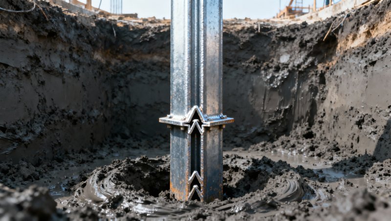
Interlock design is arguably the most underestimated specification variable. Interlocks are not passive joints—they’re dynamic load-transfer interfaces. In dense clay, soil wedging into the interlock cavity during driving creates significant lateral confinement pressure. A tight, symmetrical interlock (e.g., straight-lock or modified tongue-and-groove) resists this wedging better than an open, asymmetrical one. But overly tight tolerances increase frictional resistance during insertion—especially if interlock surfaces lack uniform surface finish or have micro-scale burrs from cutting or cold-forming. Real-world field data shows that interlock resistance can account for 25–40% of total driving resistance in dense clay, depending on soil plasticity index (PI > 30). That’s why standardized interlock testing per ASTM D5339—measuring pull-out force under simulated clay adhesion—is essential, not optional.
Manufacturing consistency directly impacts field performance. Variations in interlock taper, flange parallelism, or camber > L/1000 introduce cumulative misalignment over a 20-pile wall. Each misaligned pile increases resistance for the next by forcing soil displacement laterally rather than vertically. Cold-formed sections—while cost-effective—require tighter process control on roll tooling wear and springback compensation. Hot-rolled sections offer superior dimensional repeatability but come with higher unit cost and longer lead times. For projects where schedule certainty outweighs marginal cost savings, hot-rolled piles with certified interlock geometry (e.g., ±0.2 mm tolerance on interlock width) reduce the likelihood of unplanned pre-boring or jetting.
 Corrosion protection strategy also interacts with driving performance—though indirectly. Galvanized coatings add ~0.05–0.1 mm of surface thickness. While negligible for most applications, in extremely tight interlocks (clearance < 0.3 mm), even galvanizing can increase insertion resistance. More critically, if galvanizing is applied after cold forming—without proper annealing—the zinc layer may crack at interlock bends, exposing base metal to corrosion once installed. This doesn’t affect initial driving, but undermines long-term integrity in aggressive groundwater environments. For such cases, hot-dip galvanizing prior to forming—or post-forming with controlled thermal cycles—is preferable. Galvanized Round Steel used in ancillary components like guide frames or bracing systems must meet the same coating adhesion and thickness standards (ASTM A123, EN ISO 1461) to avoid premature degradation under cyclic loading.
Ultimately, specifying steel sheet piles for dense clay isn’t about selecting the strongest or thickest option. It’s about matching geometry, material ductility, interlock precision, and manufacturing consistency to the soil’s mechanical memory. A pile that drives smoothly in medium sand may stall repeatedly in stiff clay—not because it’s undersized, but because its flange-to-web ratio amplifies lateral soil resistance, or its interlock geometry traps clay instead of shearing it cleanly. Project managers should require mill test reports showing actual interlock dimensions—not just nominal values—and request third-party verification of section properties if the pile will be driven near its theoretical capacity limit. When soil data indicates su > 120 kPa and PI > 35, treat interlock tolerances and flange flatness as critical quality gates—not secondary specs.
No single specification dominates. But when geometry, thickness, material behavior, and interlock design align with dense clay mechanics, driving resistance becomes predictable—not prohibitive.
Corrosion protection strategy also interacts with driving performance—though indirectly. Galvanized coatings add ~0.05–0.1 mm of surface thickness. While negligible for most applications, in extremely tight interlocks (clearance < 0.3 mm), even galvanizing can increase insertion resistance. More critically, if galvanizing is applied after cold forming—without proper annealing—the zinc layer may crack at interlock bends, exposing base metal to corrosion once installed. This doesn’t affect initial driving, but undermines long-term integrity in aggressive groundwater environments. For such cases, hot-dip galvanizing prior to forming—or post-forming with controlled thermal cycles—is preferable. Galvanized Round Steel used in ancillary components like guide frames or bracing systems must meet the same coating adhesion and thickness standards (ASTM A123, EN ISO 1461) to avoid premature degradation under cyclic loading.
Ultimately, specifying steel sheet piles for dense clay isn’t about selecting the strongest or thickest option. It’s about matching geometry, material ductility, interlock precision, and manufacturing consistency to the soil’s mechanical memory. A pile that drives smoothly in medium sand may stall repeatedly in stiff clay—not because it’s undersized, but because its flange-to-web ratio amplifies lateral soil resistance, or its interlock geometry traps clay instead of shearing it cleanly. Project managers should require mill test reports showing actual interlock dimensions—not just nominal values—and request third-party verification of section properties if the pile will be driven near its theoretical capacity limit. When soil data indicates su > 120 kPa and PI > 35, treat interlock tolerances and flange flatness as critical quality gates—not secondary specs.
No single specification dominates. But when geometry, thickness, material behavior, and interlock design align with dense clay mechanics, driving resistance becomes predictable—not prohibitive.
Previous page: Already the first one
Next page: Already the last one
Please give us a message


Please enter what you want to find