Bending changes the cross-sectional properties used to verify a steel member because the finished geometry is rarely identical to the idealized sharp-corner drawing. Corner radii, local thinning, flange rotation, and distortion affect area, centroid location, second moments of area, and section modulus. Cold forming also changes local material behavior through plastic strain and residual stress. A credible design calculation therefore distinguishes the geometry of the finished profile from the properties of the original flat steel and applies the relevant structural standard to the actual loading and fabrication conditions.
For formed steel, or acero conformado, the distinction between gross section properties and usable structural resistance is especially important. A larger measured yield strength in a worked corner does not automatically compensate for a reduced effective width in a slender compression element. Both effects need to be assessed under the same design basis.
From flat strip to finished cross section
When a strip is bent into a channel, angle, or lipped profile, material follows a curved path through each corner. The outside of the bend is stretched and the inside is compressed. The neutral surface, where longitudinal strain associated with the bend is approximately zero, does not necessarily remain at the original mid-thickness during plastic forming. Its position is influenced by bend radius, thickness, material behavior, and the forming process.
These changes matter because section properties are calculated from material distribution. The gross area, A, is the sum of the material in the finished cross section. The centroid identifies the area-weighted center. The second moment of area, I, describes how that area is distributed relative to a chosen axis; the elastic section modulus, S, is I divided by the distance from the centroid to the extreme fiber on the relevant side. An asymmetric section can therefore have different section moduli at its two extreme fibers.
A profile drawn with sharp corners places material differently from one with actual radii. Substituting flat dimensions into sharp-corner formulas can overstate or understate a property, depending on the dimension convention and axis considered. The discrepancy becomes more significant when corners occupy a substantial part of the cross section or when several bends occur in a small profile.
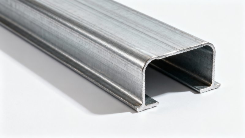
Dimensions must have a consistent reference: outside-to-outside, inside-to-inside, and centerline measurements cannot be interchanged without accounting for thickness and radius. For example, an outside flange dimension includes part of the corner region, whereas a flat-width dimension used in a local buckling calculation generally refers to a defined flat element. The governing design standard determines exactly where those widths are measured.
Thickness is not always uniform around a bend
Cold bending can reduce thickness locally, particularly near the outside of a tight bend. The degree of thinning depends on the inside bend radius relative to the original thickness, material ductility, tooling, and the strain imposed by the process. A large-radius bend in a ductile sheet and a tight bend in a higher-strength sheet should not be assumed to retain the same thickness profile.
Uniform nominal thickness is often used for section-property calculations when permitted by the applicable specification. That assumption should be distinguished from a measurement of the minimum thickness at a corner. A single low reading does not establish that the entire profile has lost the same amount of material, while a nominal sheet thickness does not prove that the bend satisfies a specified local minimum.
Measurement method also matters. Coatings, surface condition, instrument alignment, and the curvature of a corner can affect a reading. A useful inspection record identifies whether thickness was measured on a flat, at the bend, or after coating removal, and states the sampling locations. Where section properties are especially sensitive to thinning, a measured or conservatively modeled thickness distribution provides a better basis than applying the lowest local value indiscriminately to every element.
Second moment of area depends on the axis
Moving a small amount of steel away from an axis can change I more than an equal change close to that axis, because distance from the axis is squared in the calculation. A modest change in flange position can therefore affect bending stiffness more than the corresponding change in total area suggests. Springback, flange opening, and lip rotation are geometrical changes with direct consequences for the finished section.
Consider a formed channel whose flanges open slightly after release from the tooling. The gross area may remain nearly unchanged, yet the centroid and the distribution of material about both principal directions can shift. The calculated stiffness about one axis need not change by the same proportion as stiffness about the other. For an unsymmetric profile, principal axes can also be inclined relative to the drawing axes, so the product of inertia is relevant when determining bending response.
Section modulus is similarly directional. If bending puts one flange in compression and the other in tension, the distances from the centroid to the two extreme fibers govern separate elastic section moduli. Reversing the moment can change the controlling value even though the same profile is used. A tabulated single value for “section modulus” is incomplete unless its axis and reference side are clear.
These geometric properties are distinct from member stiffness and strength. Deflection under load also depends on elastic modulus, span, restraint, connection behavior, and loading. Strength additionally depends on yielding, instability, and the applicable resistance rules. A profile with a favorable gross I value can still be controlled by local or lateral instability.
Gross geometry versus effective section properties
Thin compression elements can buckle locally before the entire gross cross section reaches the assumed compressive stress. A wide, slender flange or web is more susceptible than an otherwise comparable element with greater restraint or smaller flat width. Lips, intermediate stiffeners, and adjoining elements can improve restraint, but their contribution depends on their own geometry and stiffness.
Design methods for cold-formed members address this behavior through provisions such as effective widths or other permitted approaches. Effective area and effective section modulus represent a design treatment of instability; they are not physical measurements of missing steel. Their values can change with stress distribution, loading direction, boundary conditions, and the design method. The relevant standard must be applied consistently rather than combining an effective property from one method with resistance equations from another.
For a lipped channel in bending, the compressed flange and lip deserve particular attention. A lip that looks substantial on a drawing may provide limited restraint if its dimensions or connection to the flange do not satisfy the assumptions of the chosen method. If the bending direction reverses, the previously tensioned flange becomes the compression element and the controlling effective section can change.
Distortional buckling is a separate concern: an edge-stiffened flange can rotate or displace together with its lip. Increasing gross section modulus alone does not establish adequate distortional resistance. Member length, bracing, fastener positions, and load application also influence global or distortional behavior, so section properties should be evaluated alongside the member configuration.
Cold work, residual stress, and material properties
Plastic deformation during cold forming generally increases local strength while reducing remaining ductility in the worked region. The effect is concentrated in bends, although roll forming and other processes can introduce strain into adjacent flats. The strength of a corner is therefore not necessarily the same as the strength of the original sheet or the flat portions of the finished profile.
Some design provisions permit an increase in the assumed strength of a complete cold-formed section under specified conditions. Such an allowance is a code calculation, not a blanket substitution of corner tensile results for the base-metal yield strength. Its applicability depends on the material, forming route, section geometry, subsequent processing, and governing standard. A local hardness reading alone is not sufficient to establish a design yield strength for the whole cross section.
Residual stresses remain after the forming forces are removed because different regions have undergone different amounts of plastic deformation. They are self-equilibrating in an unloaded section, but they affect the stress distribution when service loads are applied. Cutting, welding, and subsequent forming can redistribute these stresses and alter the final shape. Their presence should not be interpreted as evidence that a member is already carrying an external load equal to the residual stress.
The elastic modulus of steel is not interchangeable with yield strength. Cold work can raise yield strength without a corresponding proportional increase in elastic stiffness. For an elastic deflection calculation, multiplying the original modulus by the percentage increase in yield strength would therefore give an unjustified result.
Forming a section and curving a member are different operations
Forming a straight profile from sheet changes the cross section at its bends. Curving an already formed beam or tube along its length introduces an additional set of effects. The cross section can twist, flatten, or distort as the member is rolled or press-bent. In a rectangular hollow section, for example, wall deformation and corner movement can alter the local section properties even when the original straight length met its dimensional specification.
The finished member should be assessed at representative locations, including regions of highest curvature and transitions near straight ends. Measuring only the overall bend radius or chord does not reveal local flattening. Conversely, a profile can meet a local cross-section tolerance while failing the specified overall sweep or twist. Both scales of geometry are relevant, but they answer different questions.
Longitudinal bending can also change the location of critical stresses and interact with the intended loading. For a curved member, straight-member formulas may be inappropriate where curvature is significant relative to section depth or where the governing design method requires a curved-member analysis. The choice of model must follow the actual geometry and the applicable design provisions.
Material identification before using product data
Cold work affects stainless steel as well as carbon steel, but a product description alone does not establish the grade or the section to be analyzed. The listing for 316L Stainless Square steel rod identifies its title as 316L while the supplied material information refers to 201 stainless steel. Those designations must be reconciled against the order and material certificate before assigning mechanical properties or assessing forming behavior.
A solid square rod and a thin-walled formed square tube also require different section models. The former has material throughout its cross section; the latter has walls and corner radii that influence local buckling and thickness distribution. A listed square-bar size cannot establish the dimensions or section properties of a hollow formed profile.
Connecting tolerances to a defensible calculation
A useful section-property record states the material grade, nominal thickness, finished dimensions, inside or outside corner radii, axis definitions, and whether the values are gross or effective. For asymmetric sections, it should identify the centroid, principal-axis orientation where relevant, and section moduli for the compression and tension sides under the stated moment direction.
Nominal values and acceptance limits serve different purposes. A nominal model describes the intended profile; a tolerance assessment considers the range of acceptable finished shapes. The most unfavorable combination is not necessarily the smallest overall dimension: a change in lip angle or flange position can influence stiffness and buckling restraint without producing the smallest area. Tolerance combinations should be evaluated using the governing specification and realistic manufacturing limits.
Finally, compare like with like. A mill certificate for the starting strip supports identification of the supplied material, while a finished-section survey establishes geometry after forming. Neither document alone proves member resistance. The design conclusion follows from combining the applicable material properties, finished geometry, connection and restraint conditions, and the provisions of the selected structural standard.
Please give us a message


Please enter what you want to find