Local buckling can reduce the usable compression and bending resistance of cold-formed steel framing before the entire cross-section reaches yield. When a thin stud or joist appears adequate using gross-section properties but fails a design check, the cause may be buckling of its flange, web or lip. The practical response is to evaluate the actual section geometry and loading with the applicable cold-formed steel design method, rather than relying on gross area or nominal yield strength alone.
For an evaluator reviewing acero conformado en frio, the distinction matters at both member selection and connection detailing. A section may have sufficient material strength yet be sensitive to the width-to-thickness ratios of its compression elements, restraint conditions or a concentrated load near a support.
What happens when a plate element buckles?
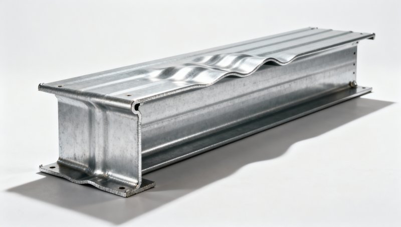
Cold-formed framing members are assembled geometrically from slender plate elements: webs, flanges, edge lips and, in some profiles, intermediate stiffeners. Under compression, an individual element can bow out of its original plane while the member as a whole remains essentially straight. In bending, local buckling generally initiates in the compression region, which may be confined to part of the section.
Local buckling does not automatically mean the member has exhausted its capacity. Depending on the section and design method, a plate can carry additional load after buckling by redistributing stress toward its supported edges. Design rules account for this behavior rather than assuming that the entire compressed element remains uniformly effective. The calculated resistance can therefore be lower than a simple gross-section yield calculation suggests.
A wide flange illustrates the issue. Its junction with the web provides restraint along one edge, while a lip may stiffen the other edge. The flange’s behavior depends not only on its width and thickness but also on how effectively the lip and adjacent elements support it. Treating each part as an isolated flat plate without the restraint assumptions required by the chosen standard can give a misleading result.
Separate local buckling from other instability modes
Thin-walled members can buckle in several ways, and each mode requires attention. A calculation that addresses local plate buckling alone is not a complete member design.
- Local buckling: Individual plate elements deform, generally without significant movement of their junctions. Width-to-thickness ratios and edge support are central to the assessment.
- Distortional buckling: A portion of the cross-section, often a flange-and-lip assembly, moves or rotates relative to the rest. Lip dimensions and restraint influence this mode.
- Global buckling: The member deforms over a longer length through flexural, torsional or flexural-torsional buckling. Member length, end conditions and bracing are important.
These modes can interact. For example, reducing the spacing of lateral braces may improve global stability without eliminating local buckling of a slender compression flange. Similarly, adding a lip can improve local edge restraint but may change the section’s distortional behavior. The governing design provisions determine how each limit state and relevant interaction is checked.
Which section details drive the result?
Flat width and design thickness
The width-to-thickness ratio is a primary indicator of plate slenderness. A wider flat element or a thinner sheet tends to be more susceptible to local buckling. The relevant width is the flat portion defined by the applicable standard, not necessarily the overall outside dimension shown on a profile drawing. Corner radii and bends affect the flat widths and should not be ignored when translating a drawing into calculation inputs.
Thickness deserves particular scrutiny when comparing catalogues. Confirm whether a listed value is base-metal thickness or includes a protective coating, and use the design thickness required by the governing provisions. Nominal, minimum delivered and measured thicknesses are not interchangeable without checking the relevant rules. A thickness discrepancy also affects section properties and may change which instability mode governs.
Support at the plate edges
A plate supported along both longitudinal edges generally behaves differently from an outstand element supported along only one. Webs and flanges are connected to other elements, but those elements are themselves deformable. Edge lips, return folds and intermediate stiffeners can improve restraint; their contribution depends on dimensions and the design method. A lip should not be assumed fully effective simply because it is present on the drawing.
Perforations complicate the picture. Service holes in a stud web can change the local stress path and affect resistance near the opening, particularly where concentrated forces or connections occur. Check the size, shape, spacing and location against the conditions of the selected design provisions or a supported engineering assessment. Gross-section properties for an unperforated profile should not be transferred automatically to a punched member.
Stress distribution and load direction
An element under uniform axial compression is not evaluated in exactly the same way as one subject to a bending stress gradient. The compression zone, supported edges and stress distribution influence the calculation. Reversing a load can put a different flange into compression, so a joist checked for downward loading may also need a separate check for uplift or load reversal.
Connections can introduce eccentricity. A stud loaded through an offset track, a joist with load applied away from its shear center, or a member with an eccentric attachment may experience combined axial force and bending. Assess the resulting stresses and required interaction checks; a nominally axial load does not guarantee uniform compression across the section.
From elastic buckling to design resistance
Elastic local buckling stress is a useful indicator of sensitivity, but it is not necessarily the final design stress. The design route depends on the adopted standard and method. Two approaches encountered in cold-formed steel design are the effective width method and the direct strength method.
Effective width methods represent nonuniform post-buckling stress by reducing the effective portions of slender compressed elements. The resulting effective area or section modulus is then used in the applicable resistance equations. For bending, the effective section can shift the neutral axis, so the compression region and effective properties may require iterative calculation. Follow the standard’s procedures for the specific element, stress pattern and stiffener arrangement.
The direct strength method uses the gross-section yield or yielding reference resistance together with elastic buckling information for the relevant modes to determine nominal strength under its prescribed equations and applicability limits. Elastic buckling analysis must represent the actual cross-section, material assumptions and restraint conditions. A software output labeled “local” should be reviewed against the associated mode shape; a numerical minimum alone does not establish that the correct mode has been identified.
Neither approach permits arbitrary mixing of factors, equations or section properties. A reported nominal strength is also not necessarily the available design strength: apply the resistance or safety factors and load combinations required by the governing design framework. Calculations should identify the standard edition, method and assumptions clearly enough to be reproduced.
A practical review when a framing member fails a check
Start with the failure reported by the calculation, not with an assumption that the steel grade is too low. A local buckling failure calls for a different response from excessive deflection or global instability.
- Verify the model. Match web depth, flange width, lip dimensions, corner radii, thickness and hole pattern to the proposed profile. Confirm which dimensions describe flat widths and which describe overall dimensions.
- Reconstruct the loading. Check the compression region, load combinations, eccentricities and whether the member is subject to axial force, bending, shear or a combination. Review both load directions where reversal is relevant.
- Inspect restraint assumptions. Record end conditions and bracing for global behavior, then assess the edge restraint and stiffener details used in the local and distortional checks. Do not treat a connection as continuous restraint unless its layout and stiffness justify that assumption.
- Confirm the design method. Check effective properties or elastic buckling inputs, mode identification, applicable limits, and the factors used to obtain design resistance.
- Revise the section and recheck. Consider a thicker sheet, narrower flat elements or a different stiffener arrangement where feasible. Recalculate all relevant limit states rather than assuming that an improvement to one mode improves every other check.
A higher yield grade is not always the most effective correction. For a slender element, the design method may reduce the proportion of the section considered effective as yield strength increases. The resulting capacity must be calculated; it should not be assumed to rise in direct proportion to the grade designation. Greater thickness may affect both plate slenderness and section properties, but it also changes weight, connections and fabrication requirements.
At supports and concentrated loads, review web crippling and applicable bending-and-web-crippling interaction separately. Web crippling is a localized failure associated with bearing and concentrated forces; passing a local plate buckling check does not establish that the web can resist a reaction or point load. Bearing length, load location, fasteners and the relevant support condition are part of that evaluation.
Standards and documentation
In North American work, cold-formed steel member design is commonly assessed using the applicable edition of AISI S100, together with the building code and loading provisions adopted for the project. European work commonly uses EN 1993-1-3 alongside the other applicable parts of Eurocode 3 and the relevant National Annex. The edition, jurisdiction, material specification and project requirements must be established before selecting equations or resistance factors.
Standards do not make all manufactured sections interchangeable. Request a dimensioned profile, base-metal thickness, specified steel grade, relevant material properties and details of holes or stiffeners. Where design tables or software are supplied, determine which standard edition, method, bracing assumptions and load conditions underpin the stated capacities. A table value for one unbraced length or load arrangement should not be applied to another without checking its basis.
For a retaining or water-retaining application, the alternative framing system may be steel sheet piling rather than a thin-walled stud or joist. The available Hot Rolled Steel Sheet Pile includes U-shaped carbon-steel profiles, with listed grades including S275 and S355. This is a different product and design problem: its wall action, interlocks, ground or water pressures, support conditions and applicable standards must be assessed separately. It should not be substituted into a cold-formed framing calculation using the same section assumptions.
Before accepting a framing design, retain the governing local, distortional and global checks alongside the geometry and restraint assumptions used to produce them. If the supplied section differs from the model—particularly in thickness, lip dimensions or perforations—the resistance should be reassessed for the section actually proposed.
Please give us a message


Please enter what you want to find