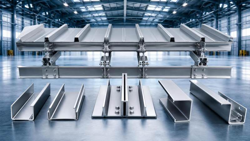
Cold formed steel design starts with section behavior under codified loading, not with nominal thickness alone. Thin-walled members can deliver high strength-to-weight efficiency, but their capacity depends on how the shape was formed, how the load is introduced, and whether local buckling, distortional buckling, or global instability controls before the base steel reaches its full yield strength. In practical evaluation, flange width-to-thickness ratio, lip geometry, web depth, corner radii, hole placement, and bracing spacing often matter as much as the listed steel grade.
The term cold formed steel usually refers to sheet or strip steel shaped at room temperature into profiles such as C sections, Z purlins, sigma sections, tracks, studs, hats, and custom roll-formed channels. Because the forming process can increase strength in the corners and along bent regions, published section properties may differ from a simple flat-sheet assumption. Even so, design capacity is rarely governed by material strength alone. For many members, the controlling limit state is instability of a slender plate element or interaction between elements under compression and bending.
Load Limits Depend on Limit State, Not a Single Number
When a drawing or specification asks for the load limit of a cold formed steel member, the answer normally changes with support condition, bracing, fastener pattern, serviceability criteria, and loading direction. A roof purlin under gravity load may be limited by bending strength, lateral-torsional buckling, web crippling at supports, or deflection. A wall stud can be controlled by axial compression with bending from wind, while a floor joist may fail serviceability first because vibration or deflection becomes unacceptable before the calculated ultimate strength is exhausted.
Several checks tend to govern:
- Local buckling: individual plate elements such as webs or flanges buckle between their supporting folds or stiffeners.
- Distortional buckling: the flange-lip combination rotates and deforms together, which is common in lipped channels.
- Global buckling: flexural, torsional, or flexural-torsional buckling of the full member.
- Web crippling and bearing: concentrated reactions near supports or point loads can damage thin webs even when bending stress is moderate.
- Connection limit states: screw pull-out, pull-over, bearing, net section rupture, and slip can reduce usable capacity.
For this reason, cold formed steel should be reviewed through effective section properties or direct strength procedures required by the applicable standard, rather than through hot-rolled steel habits. A member that appears conservative by gross area may become inadequate once effective width reductions are applied. Conversely, a profile with well-proportioned stiffened elements may perform better than a heavier but poorly braced alternative.
Span Evaluation Needs More Than Section Modulus
Span is often treated as a simple lookup issue, yet the actual usable span of cold formed steel changes quickly with loading pattern and restraint. A Z purlin in a continuous roof system can usually span farther than a simply supported single span member of similar depth because continuity lowers midspan moments. However, that advantage can be lost if lap lengths are too short, support alignment is poor, or the sheeting does not provide the assumed diaphragm restraint.
Deflection criteria often become decisive in long, light members. Roof elements may need tighter limits where brittle finishes, drainage slope, or cladding alignment matter. Wall studs may need stricter serviceability control to avoid visible movement, cracking of finishes, or poor fit around openings. The span that satisfies strength might still be rejected if it causes ponding risk, cladding distress, or unacceptable dynamic response.
Common span variables include member depth, thickness, yield strength, flange and lip proportions, bracing points, load duration, and whether uplift combinations are relevant. In external envelope applications, designers should also consider that suction can reverse the stress pattern, making the compression flange shift and changing which buckling mode governs.
Where heavy point loads, suspended services, or equipment supports are expected, span tables may be insufficient on their own. Thin-walled members behave differently from solid rolled sections under concentrated loading. Reinforcement plates, nested sections, sleeves, or local bearing stiffeners may be required near supports and hangers.
Material and Section Details That Change Structural Performance
Base metal thickness and coating thickness should not be confused. Corrosion protection layers are important for durability, but the structural design thickness is based on the metallic base steel according to the governing standard and product declaration. This distinction affects calculated area, inertia, and screw engagement. In technical review, one of the common errors is reading a nominal outside measurement as if it represented design thickness.
Cold forming also introduces residual stresses and geometric sensitivity that are not usually critical by themselves, but they become relevant in slender shapes. Hole patterns for services or fixing can further reduce strength if placed near high-stress regions. A web opening close to a support, for example, may interfere with shear flow and web crippling resistance. Punching patterns used for modular framing should therefore be assessed as part of the structural section, not as a secondary fabrication detail.
Galvanized material is widely used in cold formed steel framing and purlin systems because exposed thin sections have more surface area relative to weight and can corrode faster if left unprotected in humid or chemically aggressive conditions. That does not mean any coated section is suitable for every environment. Marine exposure, trapped moisture, cut edges, contact with dissimilar metals, and damage during installation can all shorten service life. Drainage paths, ventilation, and maintenance access remain part of good design.
Where Misjudgment Usually Happens
A frequent mistake is transferring hot-rolled steel assumptions directly into cold formed steel evaluation. The shapes may look similar on paper, but thin-walled sections are more sensitive to eccentric loading, restraint quality, and connection stiffness. Another recurring issue is treating test values from one profile series as interchangeable with another series that has different corner geometry or lip dimensions. Small shape changes can move the controlling buckling mode enough to alter design strength.
Support conditions are another source of error. A track, cleat, or seat angle that appears rigid may actually allow rotation or local deformation. If the end reaction is introduced through one flange instead of through the web centerline, torsion can increase. Screw spacing also matters. An otherwise adequate section may lose composite restraint if fasteners are spaced farther apart than assumed in design, or if the attached sheeting is thinner than expected.
Fire exposure deserves a separate note. Cold formed steel members heat quickly because of their low mass. When fire resistance is required, membrane protection, board systems, insulation arrangement, and tested assembly configuration may become more important than the steel section alone. Capacity at ambient temperature should not be treated as a direct indicator of performance in fire conditions.
Connections Often Control the Real Capacity
In built-up cold formed steel systems, the connection layout is part of the structural behavior. Self-drilling screws are common because they are fast to install and suitable for thin-gauge steel, but screw type, diameter, edge distance, steel thickness combination, and pull-over resistance of the connected sheet all affect performance. Bolted or welded details may be used in heavier assemblies, though heat from welding can alter coatings and may require follow-up corrosion treatment.
Moment transfer in cold formed steel framing is often lower than assumed unless the detail is explicitly designed and tested for rotational stiffness. Many systems behave closer to pinned construction even when the joint looks substantial. This influences span, sway, and load path. Bracing members, bridging channels, and sag rods are therefore not minor accessories; they can be essential to reaching the stated member capacity.
Where a mixed-material structure uses rods, anchor elements, or secondary bracing beside thin-walled framing, round carbon steel products may be selected for localized tension, railing, utility supports, or connection hardware. In such cases, consistency between the primary framing specification and adjacent support materials matters more than using a single product family everywhere. A related reference in general steel applications is Hot rolled Carbon Steel Round Bar, which is available in grades such as S235JR, S355JR, ST37, ST52, and 30CrMo, with diameter options extending from small bars to large sections and surface conditions including untreated, galvanized, passivated, or oiled finishes. That kind of material belongs to a different structural category from cold formed profiles, so substitution should never be made without recalculating stiffness, connection behavior, and corrosion compatibility.
Structural Advantages in the Right Application
The main structural advantage of cold formed steel is efficient use of material. Because steel is placed away from the neutral axis through folded geometry, a relatively light section can develop useful stiffness and bending resistance. This becomes attractive in secondary framing, wall systems, roof purlins, floor joists, equipment housings, mezzanine elements, and modular assemblies where dead load reduction supports easier transport and handling.
Dimensional consistency is another practical advantage. Roll-formed production can hold repeatable profiles over long runs, which helps when projects rely on panelized or prefabricated installation. Standard punching, pre-cut lengths, and lighter individual member weight can simplify site logistics, especially where crane time is limited or interior work must proceed in constrained areas.
There are also procurement and fabrication benefits tied to section variety. Custom lips, stiffeners, web holes, and nesting arrangements can often be produced without the same mass penalty associated with heavier rolled sections. That flexibility allows engineers to tailor members to cladding systems, service integration, and transport limits. Still, customization introduces a verification burden: any nonstandard shape needs traceable section properties, tolerances, and a design method aligned with the chosen code.
Transport, Storage, and Installation Affect Performance Later
Cold formed steel is light enough that transport damage is sometimes underestimated. Long thin sections can twist, bow, or suffer edge damage if bundles are not supported correctly. Distortion introduced before erection may reduce fit-up quality and alter the member’s initial imperfection level, which matters in slender compression elements. Storage on uneven ground, exposure to standing water, or prolonged contact with incompatible materials can also create later problems that are not visible in mill certificates.
During installation, temporary bracing should remain in place until the full load path is established. A purlin line or stud wall that becomes stable only after sheathing attachment is vulnerable during partial assembly. Fastener substitution in the field is another recurring issue. Changing screw length, head type, drill point, or coating can affect both structural performance and durability.
Tolerances should be reviewed with realistic erection conditions in mind. In thin-gauge systems, a small alignment error can accumulate across many members, producing unintended eccentricity at tracks, panel joints, and cladding interfaces. Where openings are frequent, local reinforcement around doors, windows, penetrations, and equipment supports should be treated as part of the primary design package, not left to site improvisation.
Reading Specifications Without Overstating Capacity
A solid technical review of cold formed steel usually compares the design basis, section geometry, steel grade, coating designation, connection assumptions, and span criteria in one place. If one document cites ASTM dimensions, another cites EN tolerances, and a third uses a proprietary span table, the interfaces need careful reconciliation. Differences in notation can hide important issues, including whether the section properties are gross, net, effective, or based on a tested assembly.
The practical question is not whether cold formed steel is strong in general terms. It is whether the exact profile, under the exact restraint and connection conditions, remains within strength and serviceability limits for the specified loading combinations. Once that is answered with the correct standard and section data, cold formed steel becomes a precise and efficient structural option rather than an assumed lightweight substitute for heavier steel shapes.
Please give us a message


Please enter what you want to find