A clean cut is rarely “just a cut” in structural steel work. The choice made at the cutting station affects fit-up at the welding bay, coating preparation, assembly time, and the number of parts that return for correction. An operator cutting a deep beam flange for a connection plate faces a different problem from one trimming light-gauge cold-formed sections or processing repetitive channel lengths. The fastest machine is not always the fastest route to finished parts.
For practical structural steel cutting, the goal is to match the process to material grade, section thickness, edge-quality requirement, tolerance, batch size, and the work that follows. Plasma, laser, oxy-fuel, saw cutting, and abrasive methods all have a place. Their value becomes clearer when they are judged by the complete production flow rather than by cutting speed alone.
Start with the edge the next operation needs
Before selecting a machine or setting parameters, ask what happens after the cut. A rough edge hidden inside a non-critical fabricated assembly may be acceptable after quick cleanup. A weld-preparation edge, a visible architectural member, or a part that must locate precisely in a bolted connection demands much more control.
The most useful questions for an operator are straightforward:
- What steel is being cut: carbon structural steel, weathering steel, stainless steel, or a coated product?
- What is the actual thickness at the cut line, especially on tapered flanges or built-up members?
- Does the part need a square edge, a bevel, a hole, a cope, or a complex contour?
- How much edge preparation can the downstream team realistically absorb?
- Is the job a one-off repair, a mixed batch, or a repeated production run?
- Will heat tint, a heat-affected zone, or surface contamination create a problem later?
These questions prevent a common mistake: choosing a cutting method solely because it is available. A low-cost thermal cut can become expensive if every piece needs grinding before welding. Likewise, a highly accurate laser cut may be unnecessary for long stock lengths that will be drilled and fitted with generous fabrication allowance.
How the main cutting methods behave in real fabrication
Oxy-fuel cutting: dependable for thick carbon steel
Oxy-fuel remains a workhorse for thick carbon-steel plate, heavy beam components, and large fabricated sections. The process preheats the steel and uses an oxygen jet to oxidize and remove material. It is relatively tolerant of outdoor conditions and is well suited to portable cutting where taking a large member to a CNC table is impractical.
Its limitations matter. Oxy-fuel produces a wider heat-affected zone than laser cutting and generally more than plasma. The upper edge may round, the lower edge can develop slag, and long cuts on thin material can cause distortion. Accurate torch height, steady travel speed, correct tip condition, and clean fuel-gas settings are essential. If the cut is too slow, the kerf becomes wide and heavily oxidized; too fast, it leaves lag lines and stubborn dross.
Oxy-fuel is intended primarily for carbon and low-alloy steels. It is not a suitable general solution for stainless steel, aluminum, or many non-ferrous alloys because their oxidation behavior does not support the same cutting reaction.
Plasma cutting: the flexible production choice
Modern plasma cutting is often the most adaptable option for structural fabrication. It handles carbon steel, stainless steel, and aluminum; cuts profiles, plates, channels, and many formed sections; and reaches useful speeds across common workshop thicknesses. High-definition plasma systems can produce impressively consistent edges when consumables, gas selection, torch height control, and program parameters are maintained correctly.
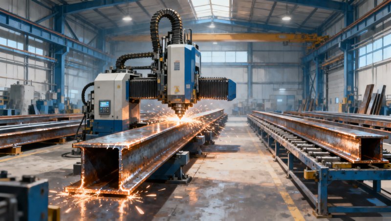
For beams, angles, and channels, plasma’s real advantage is versatility. CNC systems can combine trimming, coping, slotting, hole cutting, marking, and bevel operations in one handling cycle. That reduces layout work and keeps part identification closer to the cutting process.
However, plasma cut quality is directional. The “good” side of the cut may be cleaner than the opposite side due to torch rotation and lead angle. Operators should orient critical edges appropriately, inspect bevel angle regularly, and replace worn electrodes and nozzles before quality visibly drifts. Consumables that appear usable can still create inconsistent kerf width, angled edges, or incomplete pierces.
Laser cutting: precision where thickness and geometry allow
Laser cutting offers narrow kerfs, small heat input, and excellent contour accuracy on suitable material thicknesses. It is particularly valuable for connection plates, tabs, brackets, gussets, light structural parts, and repeated components with detailed geometry. When the part must move directly from cutting to bending, fitting, or assembly, laser accuracy can eliminate a surprising amount of manual adjustment.
That said, laser is not automatically the answer for every structural member. Thick sections may fall outside the most economical operating range, and reflective or surface-contaminated material requires appropriate equipment and controls. Heavy mill scale, rust, oil, and uneven material can affect pierce performance and edge consistency. Long beams and channels also introduce handling constraints that are separate from the laser’s cutting capability.
Where laser cutting is used for stainless material, clean handling is especially important. Carbon-steel dust, shared grinding tools, or contaminated support surfaces can undermine corrosion performance around an otherwise precise cut.
Saw cutting: often the cleanest answer for straight lengths
Band saws, circular cold saws, and other mechanical methods do not have the visual drama of thermal cutting, but they are frequently the most sensible choice for straight cuts in bars, tubes, channels, angles, and smaller beams. A well-maintained saw can produce a square, low-heat edge with minimal oxidation and little distortion. This makes it attractive when the cut face is a critical fit-up surface or when coating and welding procedures discourage a wide heat-affected zone.
Saw cutting is less efficient for intricate shapes, internal features, and complex copes. Blade selection, clamping, feed pressure, coolant, and chip removal determine whether the process stays productive. Pushing a dull blade through structural material may produce poor squareness, work-hardening on certain alloys, and a finish that still needs correction.
Abrasive cutting and handheld tools: useful, but not a production standard
Portable abrasive saws, cut-off wheels, and handheld grinders are valuable for field adjustments, small corrections, and access-restricted work. They are not the preferred primary process for parts requiring repeatable length, clean bevel geometry, or documented dimensional consistency. Sparks, dust, disc wear, and operator-dependent accuracy increase both safety and quality risks.
Use them deliberately: mark clearly, support the workpiece, verify the final dimension after the cut, and remove sharp edges rather than assuming the wheel has left a safe finish.
Clean edges are created by setup, not by machine name
A premium CNC system cannot compensate for unstable material support or poor part programming. Conversely, a conventional process can deliver reliable work when the setup is disciplined. For clean structural steel cutting, several controls deserve daily attention.
Support the member without trapping the kerf
Beams and long profiles can move as residual stress is released. If a cut-off piece is unsupported, it may pinch the blade, close against the torch path, or tear the final edge as it falls. Place supports on both sides of the cut, account for the center of gravity, and plan the sequence for long members. With nested plate, small parts should not tip, collide with the torch, or shift before the program is complete.
Allow for kerf and heat movement
Kerf width is not a minor programming detail. It directly affects hole size, slot width, tab fit, and final part dimensions. Thermal processes also introduce heat movement, particularly in thin plate, narrow strips, and asymmetrical shapes. Correct lead-ins, lead-outs, cut order, bridge tabs, and spacing between adjacent cuts help control distortion.
For critical dimensions, measure the first-off part rather than trusting a previous program. Confirm overall length, diagonal, hole position, squareness, and bevel angle before committing to a large batch. This short pause is usually far cheaper than sorting a full nest of nonconforming parts.
Choose the right pierce strategy
Many edge defects begin before the contour cut starts. A poor pierce can leave a large crater, spatter, or hardened zone that interferes with a nearby weld or bolt hole. Keep pierces away from critical finished edges where possible, use appropriate pierce height and delay, and consider ramping or lead-in geometry for thicker material. On coated or heavily scaled steel, a test pierce can reveal whether surface preparation is needed.
Cut quality should be inspected in the language of fabrication
Operators do not need to turn every job into a laboratory exercise, but visual inspection should be systematic. Look for a reasonably square edge, uniform drag lines, limited adherent dross, complete cut-through, and no excessive gouging at starts and stops. Check for sharp burrs that can injure handlers or interfere with coating.
Dimensional checks should reflect the drawing and the joint design. A part that is within length tolerance but has an incorrect bevel may still create a poor weld root condition. A hole that looks round but sits off-center can force field reaming and delay erection. When specifications reference standards such as ASTM, EN, JIS, or GB, confirm the required material condition and project tolerances rather than assuming one general shop practice fits every order.
For welded assemblies, inspect thermal-cut edges before welding. Heavy oxide, slag, moisture, paint, and laminations should be addressed according to the welding procedure and project requirements. The best cutting workflow leaves welders a stable, accessible joint—not a hidden cleanup task.
Stainless and cold-worked bar stock require a different mindset
Not every job involves large carbon-steel beams. Smaller structural details, fixtures, brackets, and equipment components may use stainless bar or flat stock. In these cases, avoiding contamination and excessive heat becomes as important as achieving a neat edge. Dedicated stainless brushes and abrasives, clean work surfaces, and suitable coolant or shielding practices help protect the finished surface.
For example, the 306 Stainless Square steel rod range includes square-bar dimensions from 18 mm to 47 mm, with options for bright polished, rough-turned, matte, and other surface conditions. When cutting this type of stock, saw cutting is often preferred for straight, repeatable lengths; laser or plasma may suit shaped components if the post-cut surface and heat effect are evaluated. Because the listed material information identifies 201 stainless steel, the applicable drawing, material certificate, and project specification should always be checked before selecting cutting parameters or welding consumables.
Cold-worked stainless can respond differently from mild steel during machining and cutting. Avoid excessive friction, maintain sharp tooling, and do not let a grinding operation smear carbon-steel debris onto a visible stainless surface. A bright finish can be lost quickly through careless handling, even when the dimension is correct.
Choosing for throughput means looking beyond meters per minute
Throughput includes loading, marking, alignment, cutting, unloading, cleanup, inspection, and transfer to the next station. A plasma table may cut quickly but lose its advantage if operators spend too long removing dross from every part. A saw may have a slower cut cycle yet win on total time when straight sections can go directly to drilling or assembly with no edge dressing.
For repetitive structural packages, organize parts by material type, thickness, and downstream process. Cut parts needing the same gas, consumables, bevel settings, or finishing requirement together where practical. Keep programs clearly labeled with revision control, especially for connection details. A wrong revision cut accurately is still scrap.
Material utilization also deserves attention. Nesting software can reduce offcut, but usable remnants should be identified and stored in a way that preserves traceability. Random offcuts without grade, heat, or thickness information may become unusable inventory. Reliable manufacturers and exporters commonly support this discipline by supplying structural products to the required standard and maintaining clear material documentation through receiving and processing.
A practical selection guide at the machine
If the work is thick carbon steel with long contours or large profiles, oxy-fuel remains a robust choice when heat effects and cleanup are acceptable. If the job includes mixed materials, coping, holes, and medium-to-high production volume, CNC plasma is often the most balanced solution. If tight geometry, narrow kerfs, and low heat input are central to the part design, laser cutting is worth considering within its practical thickness and handling range. If the cut is straight, the member is bar, channel, angle, or tube, and a clean square face matters, choose a saw before reaching for a torch.
The best structural steel cutting decision is therefore not a contest between technologies. It is a controlled choice based on the required finished edge. When operators connect cut quality to welding, fit-up, coating, safety, and handling, they stop measuring success at the moment the part separates from the stock. That is where cleaner edges and genuinely faster throughput begin.
Please give us a message


Please enter what you want to find