A 12 mm wire rope is suitable for a lift only when the rated capacity of the complete lifting arrangement meets or exceeds the forces expected during that lift. Diameter identifies the rope size; it does not establish a universal lifting capacity. Construction, steel grade, termination, sling geometry, rope condition and the equipment in which the rope is installed all affect the decision.
Start with the intended use: is the rope part of a crane hoist, a fabricated sling, or a temporary winching arrangement? Each application has different rating information and operating limits. A breaking-strength figure on its own is not permission to lift a load of that weight.
Breaking strength is not the lifting capacity
Manufacturers may state a rope's minimum breaking force, often expressed in kilonewtons, and a working load limit or rated capacity for a finished sling. These figures describe different things. Breaking force concerns the rope under specified test conditions; a lifting rating accounts for the intended application and its required design factor. The applicable factor is not a universal value that can be selected without knowing the equipment, configuration and governing requirements.
A finished sling also includes terminations such as eyes, ferrules or sockets. Its rating must reflect the completed assembly and its permitted use. Do not take the breaking force of bare rope, divide it by a guessed safety factor and treat the result as an approved sling rating. Use the identification and load information supplied for the assembly, including its configuration and hitch.
Units deserve attention. A force in kilonewtons is not a mass in tonnes, and neither value should be compared with a load in kilograms without a correct conversion. Even after conversion, a breaking force remains a breaking force, not a working rating.
For a hoist rope, the equipment manufacturer specifies the compatible rope and operating limits. The crane's rated load chart governs the machine as configured, while the rope and reeving must also be suitable. A replacement rope of the same nominal diameter is not automatically an acceptable substitute.
Define the load before comparing ratings
Use a documented load weight wherever possible. Include the lifted item, attachments that remain on it, lifting beam, slings, shackles and other suspended rigging as required by the equipment's load chart and lift plan. Confirm whether a quoted weight is a bare component or a shipping weight that includes packaging and temporary supports.
Unknown ground adhesion, trapped water, soil on an extracted component or a load caught on an obstruction can produce forces beyond the calculated suspended weight. Stop and resolve the restraint rather than attempting to overcome it by pulling harder. A scale reading taken after the load has broken free does not necessarily capture the peak force during extraction.
For example, a cofferdam project may involve lifting Steel Sheet Piles before installation or after extraction. The mass of a clean, free sheet is only the starting point: attached lifting gear, the sheet's center of gravity, water and any resistance at the extraction point affect the lift assessment. Pulling a sheet free requires an engineered extraction method and equipment rated for that operation; a suspended-load calculation alone does not establish the required line pull.
The load's center of gravity matters as much as its total weight. An off-center connection can put more force into one sling leg, cause the load to tilt, or make it slide in the hitch. Long steel members and sheets also require attention to bending, balance and the position of the lifting points.
Sling angles change the force in each leg
A two-leg sling does not necessarily carry half the load in each leg. As the legs spread and become more horizontal, their tension rises. For an ideal, balanced two-leg lift with equal leg lengths and a centered load, the tension in each leg is the load divided by twice the sine of the angle between a leg and the horizontal.
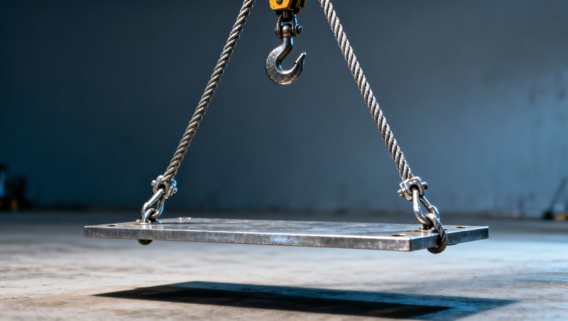
For illustration, a freely suspended 2-tonne load with two equally loaded legs at 60 degrees to the horizontal produces approximately 1.15 tonnes of force in each leg. At 30 degrees to the horizontal, the ideal tension rises to 2 tonnes of force per leg. These are geometry examples, not recommended sling ratings; they exclude additional effects such as shock loading and unequal load sharing.
Confirm how an angle is defined on the sling's rating tag or capacity chart. An angle measured from the vertical is not the same number as an angle measured from the horizontal. If the legs are unequal, the center of gravity is offset, or the attachment points cannot share the load as assumed, the symmetrical calculation is inappropriate. A lift design must account for the actual geometry and loading.
More legs do not automatically mean that the load is shared equally among all of them. Fabrication tolerances, attachment heights and load stiffness can leave one leg carrying little weight while others carry more. Use the rated arrangement and a suitable load-distribution assessment rather than dividing total weight by the number of legs.
Match the rope and its terminations to the job
Two ropes marked 12 mm can differ in strand construction, wire strength grade, core and finish. Those differences affect breaking force, flexibility, resistance to abrasion and compatibility with drums and sheaves. A more flexible construction suited to repeated bending is not automatically the best choice where crushing or surface wear dominates. The rope specification must match the equipment manufacturer's requirements and the actual service.
Terminations also set limits. A pressed eye, socket or other end fitting must be made for the rope and assembled to its prescribed procedure. A hook, shackle or master link needs an adequate rating and must fit the eye without distorting it. Forcing a large connector into a small eye can damage the rope or prevent the fitting from seating correctly. A thimble can protect an eye where specified, but its presence does not by itself establish the assembly's capacity.
Hitch choice changes the effective rating. A vertical hitch, basket hitch and choker hitch place the rope and its end fittings under different conditions. Use the sling's rated capacity for the specific hitch and angle; do not assume a basket arrangement always provides twice the vertical rating or that a choker retains the full vertical rating. The shape and condition of the load, the contact between rope and load, and the manufacturer's instructions matter.
Sharp steel edges are a particular concern. Local bending and cutting can damage a sling even when the calculated leg tension is below its rating. Select edge protection suitable for the load and rope, position it so it stays in place, and avoid arrangements that pinch or bend the rope tightly. Padding alone is not a substitute for a compatible lifting point where the edge or contact pressure presents a cutting hazard.
Adequate capacity on paper does not clear a damaged rope
Inspect the rope and fittings before use under the applicable inspection procedure. Look along the accessible length and around eyes and contact points, where damage can be concealed. Particular warning signs include broken wires, corrosion, flattened sections, kinks, heat damage, a displaced core and damaged or distorted fittings. Dirt and lubricant can hide defects, so the condition must be visible enough to assess.
Different damage patterns have different implications. Surface wear from normal contact is not the same as a sharp kink caused by mishandling; corrosion inside a rope can be more serious than a light surface stain suggests. Acceptance or rejection must follow the relevant equipment instructions and applicable inspection criteria. A rope with a kink, crushed section or other suspected serious damage should be removed from service pending assessment, not straightened and returned to lifting by assumption.
A missing or unreadable sling identification tag is also a selection problem: without a verifiable rating and configuration, the assembly cannot be matched reliably to the lift. Records of previous inspections help establish history, but they do not replace an examination of current condition. For installed hoist ropes, examine accessible portions and follow the equipment's inspection and replacement procedures, including attention to sections that pass repeatedly over sheaves or wind onto the drum.
Confirm the complete load path
The weakest rated component can govern the arrangement. A suitable rope or sling does not compensate for an undersized shackle, an unsuitable lifting lug or an overloaded hook. Ratings must apply to the direction and manner of loading: a fitting rated for an in-line pull is not automatically rated for side loading. The load's lifting points and the supporting structure also need sufficient capacity for the forces transferred through them.
Where a wire rope runs through a hoist system, drum and sheave dimensions, groove condition, reeving and end anchorage affect its service. The number of supporting rope parts changes the relationship between hook load and line tension, but friction and the equipment's reeving arrangement must be considered. Use the manufacturer's approved configuration rather than estimating hoist capacity from rope diameter and the number of visible falls.
Movement matters too. Abrupt starting, stopping, snagging or swinging can increase forces beyond a static estimate. A load that is nominally within a sling's rating can therefore create an unacceptable condition if the lift is uncontrolled or the load is restrained. Where unusual dynamics, tandem lifting or difficult extraction are expected, the lift requires an assessment suited to those conditions.
When the information is incomplete
Do not approve the lift from a diameter marking alone. Establish the identity of the rope or sling, obtain its applicable rated capacity and instructions, and reconcile those documents with the proposed load, hitch and geometry. If the rope is installed equipment, verify compatibility with the hoist documentation and the equipment's current configuration.
When the load weight, center of gravity, lifting-point capacity or extraction resistance cannot be established, resolve that uncertainty before proceeding. A different lifting arrangement, verified weighing or an engineered lift assessment may be necessary. The usable answer is the lowest applicable limit of the verified system under the actual lift conditions, not a generic capacity assigned to every 12 mm rope.
Please give us a message


Please enter what you want to find