Beams and purlins both support a steel roof, but they occupy different positions in its load path. Beams form part of the primary structure, carrying substantial roof loads toward columns or other supports. Purlins are secondary members that span between primary frames and provide support for the roof covering.
The distinction is not simply that one member is larger than the other. It depends on what each member supports, where it spans and how its loads reach the rest of the structure. Recognizing those relationships makes roof drawings easier to interpret and helps prevent unsuitable substitutions.
How roof loads move through the structure
A steel roof is an assembly of connected elements rather than a single supporting layer. In a common pitched-roof arrangement, profiled roof sheets are fastened to purlins. The purlins span from one main frame to the next, while the main frames carry their reactions to columns and foundations.
For downward loading, the basic path can be described as:
Roof covering → purlins → primary roof beams or rafters → columns → foundations.
Wind uplift can reverse the direction of the forces acting on the covering and its supports. The same connections that transfer downward forces must also be checked for the forces they are required to resist under uplift. Roof fasteners, purlin connections and primary-frame connections are therefore part of the structural system, not just assembly details.
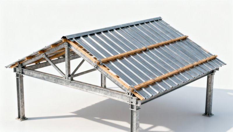
This load path is a useful starting point, but not every roof follows it exactly. A roof deck may span directly onto primary members, or purlins may be supported by trusses instead of solid beams. The names used on a drawing should always be read alongside the actual supports and connections.
What a roof beam does
A roof beam is a structural member designed to carry loads across a span to its supports. In a steel building, a primary roof beam or rafter can support a series of purlins, with the load from each purlin entering the beam at its connection point. The beam then transfers forces to columns, walls or other structural members.
In a portal-frame building, the sloping members are often called rafters. They act as part of the main frame and may be rigidly connected to columns. A roof supported by trusses has a different primary system: the truss carries loads through an arrangement of interconnected members rather than behaving as a single solid-web beam.
Structural beams are often made from rolled or fabricated steel sections, including I- and H-shaped sections. The appropriate section depends on the forces it must resist, its span, support conditions and stability requirements. A deeper section is not automatically the right choice: its strength, stiffness, restraint and connections all matter.
Beam design also involves more than checking whether the steel can carry the applied load without failure. Excessive deflection can affect roof appearance, drainage, cladding and attached components. Compression portions of a beam may need restraint against buckling, and the frame must have a stable path for forces in more than one direction.
What a purlin does
A purlin is a secondary roof member that supports the covering between primary frames. On a typical pitched roof, purlins run approximately parallel to the ridge, while the main rafters slope from the eaves toward the ridge. The purlins bridge the distance between adjacent frames; the roof sheets span across the spaces between purlins.
This arrangement allows a roof covering to be supported at intervals suited to its strength and stiffness without requiring a primary frame at every sheet support. The purlins receive loads from the covering and pass them to the beams, rafters or trusses beneath them.
Many steel purlins are cold-formed from relatively thin sheet into C or Z sections. Other profiles and hot-rolled sections can also be used where the design calls for them. Z sections can be arranged in lapped systems over supports, while C sections are used in a range of simple-span and other configurations. The section shape alone does not establish the span it can carry: thickness, steel grade, restraint, support details and loading must also be considered.
Purlins may contribute to restraining a rafter or distributing forces, but only where the structural design and connection details provide for that function. A member should not be assumed to brace another member merely because the two are in contact.
Comparing beams and purlins in a roof
These are common arrangements, not universal rules. “Beam” is a broad structural term, and a purlin itself behaves as a beam when it spans between supports. The practical distinction is that purlin describes a particular secondary roof function, whereas a primary roof beam describes a member’s place in the main supporting system.
Size can be a useful visual clue because primary members frequently carry load from a larger area of roof. It is not a reliable definition, however. A heavily loaded or long-span purlin may be substantial, and the correct classification still depends on its role in the structure.
Why spacing matters at both levels
Two different spacings are important in a purlin-supported roof. The distance between primary frames affects the span of the purlins. The distance between purlins affects the span of the roof sheets and the area of roof load delivered to each purlin.
Increasing the distance between frames can reduce the number of primary frames along a building, but it also gives the purlins a longer span. Longer spans generally increase bending and deflection demands unless the member or the structural arrangement changes. The comparison cannot be made by counting members alone.
Increasing purlin spacing has a different effect. The roof covering must span farther, and each purlin supports load from a wider strip of roof. A stronger purlin alone does not solve a roof sheet’s inadequate spanning capacity; the covering and its fasteners must also be suitable for the proposed spacing and loads.
The reverse is also important. Reducing purlin spacing does not automatically make an unsuitable primary beam adequate. The total roof load still needs to reach the foundations safely, and changing the distribution of connection points can affect the primary member’s design.
Connections, restraint and uplift
The interface between a purlin and its supporting rafter is often made using a cleat or bracket and bolts. The detail must transfer the design forces without excessive distortion or local failure. For a lapped purlin system, the lap length, bolt arrangement and continuity assumptions are part of the engineered design; a visible overlap alone does not guarantee the intended behavior.
Thin cold-formed sections can be sensitive to local buckling, twisting and deformation at supports. Their capacity depends partly on whether the roof sheeting, bridging or other elements provide the restraint assumed in design. Openings, interrupted sheeting or changes to fastening can alter those conditions.
Under wind suction, roof sheets tend to pull away from their supports. Forces then pass through the sheet fasteners into the purlins and through the purlin connections into the main frame. A roof may have adequate members for downward loading but still require closer attention to fasteners, edge zones or connections under uplift.
Bridging or sag rods may be included to maintain purlin alignment and provide restraint. Their exact structural function depends on the design. They should not be removed or treated as temporary installation aids without confirming what the roof system requires.
Roof covering is not the same as roof support
A roof covering protects the building from weather and transfers its own loads to the supporting structure. Profiled steel roofing sheets are commonly selected for both their weathering function and their ability to span between supports. Their performance depends on profile, thickness, material properties, fastener arrangement and the design loads.
Not every galvanized steel sheet product is intended to perform that role. For example, Galvanized Expanded Metal Sheet is an open-mesh material rather than a continuous weatherproof roof covering. It should not be treated as a substitute for roof sheeting, purlins or primary beams without a separate, appropriate design for its intended use.
The distinction matters because a product’s material description does not establish its structural function. Galvanizing provides a zinc coating for corrosion protection; it does not, by itself, determine whether a component has the geometry, strength, stiffness or fastening details required in a roof.
Reading a steel roof drawing
To identify a member, follow it from support to support. A component running between main frames and receiving roof-sheet fasteners is likely serving as a purlin. A member supporting those purlins and connecting into columns or a main frame is likely a primary rafter or beam. Section labels and schedules can confirm the identification.
Several drawing details help explain how the members work together:
- Frame spacing: the distance the purlins must span between primary supports.
- Purlin spacing: the distance the roof covering must span between its supports.
- Section designation: the specified profile, dimensions, thickness or weight, and material grade where shown.
- Support and lap details: whether purlins are designed as separate spans or as part of a continuous arrangement.
- Bracing and restraint: the components and connections relied upon to maintain stability.
- Roof-sheet fastening: the specified attachment pattern and fastener type, particularly where uplift is relevant.
A drawing may show members that look similar but have different thicknesses or grades. It may also use different purlin sizes at different locations because spans, loading or restraint conditions change. Matching only the visible profile is therefore insufficient when interpreting or replacing a specified component.
Can a beam replace a purlin, or a purlin replace a beam?
A steel member can perform a different function if it is designed for the forces, span, stability and connections associated with that function. The name of the section does not prohibit its use elsewhere. However, a direct substitution based only on shape or approximate dimensions is unsafe.
For example, replacing a specified cold-formed purlin with a heavier-looking section can change its weight, fixing arrangement and compatibility with roof-sheet fasteners. Replacing a primary rafter with a purlin section is an even more substantial change because the member may need to resist different forces and provide a different frame connection.
Any proposed substitution needs to account for the complete load path, including uplift, deflection, bracing and connection behavior. It should be checked against the project’s applicable design requirements and approved by the responsible structural designer before installation.
The distinction is therefore functional rather than cosmetic: purlins support the roof covering between primary supports, while primary beams or rafters carry those accumulated loads onward through the main structure. Both must be considered together for the roof assembly to perform as intended.
Please give us a message


Please enter what you want to find