A 12 mm wire rope does not have a single universal working load limit (WLL). Two ropes with the same nominal diameter can have different minimum breaking forces, while the capacity of a finished sling also depends on its terminations, configuration and applicable rating standard. The defensible starting point is the identification and rated capacity of the complete lifting assembly—not a diameter-based chart.
Where an engineering calculation is needed, use the verified minimum breaking force for the exact rope, apply the design factor and termination rules required by the relevant standard, and then check the actual lifting arrangement. A calculation cannot substitute for missing sling identification, manufacturer instructions or an inspection by a competent person.
Breaking force is not the working load limit
The minimum breaking force is a specified minimum force that a new rope must meet under the applicable test conditions. It is not the load that may be lifted in service. The WLL is the maximum load assigned for specified conditions of use; it incorporates the design assumptions and safety provisions of the applicable product standard or manufacturer’s rating.
These terms must not be confused with an actual breaking force obtained from a test. A single test result above the specified minimum does not authorize a higher WLL for other rope or for a completed sling. Nor does a certificate for the rope automatically establish the capacity of a sling made from it.
For a simplified, straight pull, the relationship is often expressed as:
Indicative working load = minimum breaking force ÷ applicable design factor
For a completed sling, the rating procedure must also address the end terminations and other requirements of the applicable standard. Some manufacturer or standard calculations already incorporate termination efficiency into the tabulated sling WLL. Applying an additional reduction without understanding the rating basis can produce a misleading result; omitting a required reduction can produce an unsafe one.
What information is needed for a 12 mm rope?
Nominal diameter is only one identifier. To establish the relevant breaking force and rating basis, match the documentation to the rope and assembly actually in use:
- Rope construction and core: Strand arrangement, wire arrangement and core type affect strength and operating behavior. A designation such as 6 × 36 is not interchangeable with every other 12 mm construction.
- Wire grade: The tensile strength grade is used in the manufacturer’s rope specification. It does not, on its own, determine the capacity of the finished assembly.
- Finish and rope type: Use the data for the specified rope, including its finish and whether it is rotation-resistant. Do not assume a value from another product is equivalent.
- End terminations: A ferrule-secured eye, socket, splice or clip arrangement must be assessed using its approved design and the relevant instructions.
- Intended use: A rope selected for a hoist drum is not automatically a rated sling, and a sling rating does not automatically cover every reeving or pulling application.
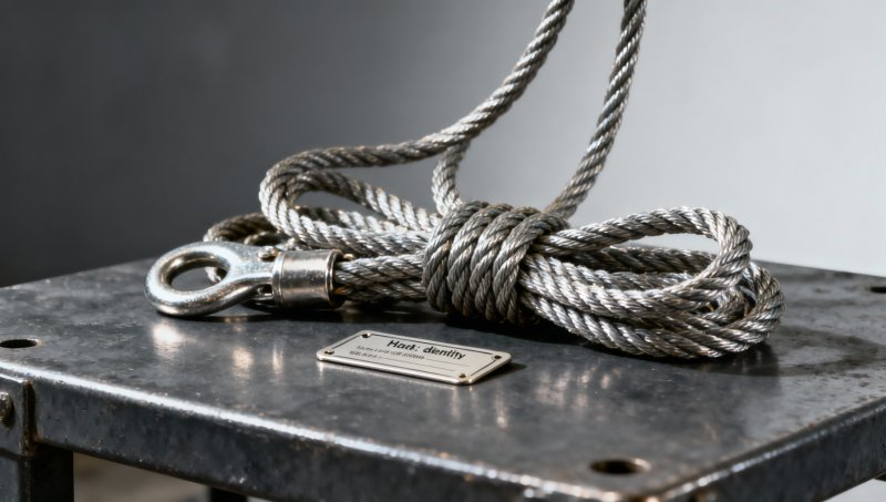
- Traceability: Identification should connect the assembly to its manufacturer, certificate or declaration, rated configuration and inspection record.
Galvanizing is an example of why finish must be interpreted in context. Steel Coil Galvanized is a coated sheet product, not a wire rope or lifting component. A zinc coating designation for steel coil cannot be used to infer the breaking force, corrosion resistance or WLL of a galvanized wire rope.
Calculate from verified data, not a generic capacity table
The following calculation illustrates the sequence. The figures are hypothetical and are not a rating for any 12 mm rope or sling.
Assume that documentation for a particular new rope gives a minimum breaking force of 80 kN. Assume also that the applicable sling rating method permits a termination efficiency of 90% and specifies a design factor of 5 for the stated configuration. If that method requires the efficiency to be applied to rope breaking force, the illustrative calculation is:
- Effective force for the calculation: 80 kN × 0.90 = 72 kN.
- Indicative WLL: 72 kN ÷ 5 = 14.4 kN.
- Mass equivalent under standard gravity: approximately 1.47 tonnes.
The tonne figure is obtained by dividing 14.4 kN by approximately 9.81 kN per tonne-force. It is a conversion of force to an equivalent supported mass, not an allowance to lift a load of that mass under any rigging arrangement. The rope value, efficiency and factor must all come from the applicable documentation; none should be assumed merely because the rope is 12 mm in diameter.
If a finished sling is supplied with a valid manufacturer’s WLL for the intended configuration, use that rating within its stated conditions. Do not recalculate upward because a rope certificate shows a higher breaking force. The completed assembly can be limited by its termination, fittings, fabrication method or the rating rules governing that assembly.
Sling angle changes the force in each leg
A sling leg does not necessarily carry half the load simply because there are two legs. As the legs become more horizontal, tension rises. For an ideal, symmetrical two-leg bridle with the load shared equally and each leg at an angle θ from the horizontal:
Force in each leg = total suspended load force ÷ (2 × sin θ)
For a 1 tonne suspended load, the approximate mass-equivalent tension in each leg is 0.58 tonnes at 60° to the horizontal, but 1.00 tonne at 30° to the horizontal. These are static illustrations, not sling selections. They assume equal sharing, a centered load and no additional effects. Rigging mass must be included when determining the total suspended load.
Angle conventions are a frequent source of error: some tables state the angle from the vertical or use the included angle between legs. Confirm the convention before applying a table. An off-center load, unequal leg lengths, different attachment heights or movement during lifting can make leg forces unequal. In such cases, the equal-sharing formula is not sufficient; the arrangement requires an appropriate engineered assessment.
A multi-leg sling’s marked WLL is normally tied to specified configurations and angle ranges. Do not add individual leg WLLs to create a new assembly rating. The connection points, master link, hooks and load itself must also be capable of sustaining the forces imposed.
Terminations and contact surfaces can govern the assembly
A 12 mm rope may have adequate specified strength while its end connection or bearing arrangement is unsuitable. The termination must match the rope diameter, construction and intended load direction, and it must be installed to the termination manufacturer’s requirements. Incorrect assembly, damaged ferrules, poorly formed eyes or incompatible fittings can invalidate a rating.
Wire rope clips are particularly sensitive to the correct type, number, spacing, orientation and tightening procedure. Those requirements vary with the clip and application; they should not be replaced by a generic rule taken from a different product. Where clip terminations are permitted, follow the manufacturer’s instructions and the applicable rules for inspection and retightening.
Bending around a pin, hook or load edge also changes the conditions from those of a straight tensile test. A small bearing diameter can concentrate stress and damage the rope. Use the sling manufacturer’s minimum bend-diameter requirements and any required capacity reductions. Protect rope from sharp edges with suitable protection, but do not assume padding alone makes an otherwise unacceptable bend or contact arrangement compliant.
Which standards apply?
The applicable requirements depend on jurisdiction, product type and use. A rope specification, a sling standard and a workplace lifting rule address different parts of the problem. Identify the governing documents before choosing a design factor or applying a capacity table.
- ISO 2408: Addresses requirements for steel wire ropes for general purposes. Rope conformity does not by itself establish the WLL of a fabricated sling.
- EN 12385 series: Covers steel wire ropes under a series of European standards, with requirements depending on the relevant part and application.
- EN 13414-1: Addresses steel wire rope slings for general lifting service, including their construction and rating requirements within its scope.
- ASME B30.9: Addresses slings, including requirements relating to use and inspection in applications within its scope.
- OSHA 29 CFR 1910.184: Contains U.S. general industry requirements for slings, including provisions concerning rated capacities and removal from service.
Use the edition applicable to the equipment and jurisdiction, together with the manufacturer’s current instructions. A factor or table taken from one standard should not be transferred automatically to a different product or service. More demanding rules may apply to particular uses, including personnel lifting; a general-purpose sling rating is not authorization for those uses.
Inspection determines whether the rating remains usable
A marked WLL describes an assembly in an acceptable condition under specified use conditions. Damage does not necessarily reduce capacity in a predictable proportion, so a visual estimate of “remaining strength” is not a reliable substitute for the applicable discard criteria.
Before use and at the intervals required by the governing rules and employer’s procedure, inspect the accessible rope, terminations and fittings. Pay particular attention to broken wires, corrosion, abrasion, distortion, kinks, crushing, heat damage and deterioration around eyes or fittings. Check that the identification and rated capacity remain legible and correspond to the assembly.
Where damage meets a removal criterion—or its significance cannot be established—remove the assembly from service and have it assessed under the applicable procedure. A missing or unreadable identification tag is not a reason to estimate the WLL from diameter; retain the sling out of service until its identity and rating are established in accordance with the governing requirements.
Measurements support inspection but do not replace it. A caliper reading can help identify diameter reduction, yet it will not reveal every internal defect or prove the construction and grade. Likewise, a newly attached tag cannot establish traceability unless the assembly’s identity and rating are supported by reliable records.
When the load is not a simple static lift
The static load calculation is only one part of the assessment. Sudden starts, stops, snagging, impact and load movement can impose forces above the load’s weight. Extreme temperatures, chemical exposure and service conditions outside the manufacturer’s limits can also affect suitability. Apply the relevant manufacturer and standard provisions rather than adding an arbitrary allowance or assuming that the design factor covers uncontrolled shock loading.
For a hoist rope, the force in a rope part depends on reeving and operating conditions; the rated capacity of the hoist is not established by dividing rope breaking force by a generic factor. The equipment manufacturer’s rope specification, installation instructions and machine rating govern the selection. Similarly, a winch or restraint application requires its own assessment rather than a sling WLL borrowed from a lifting table.
A defensible decision therefore rests on a traceable chain: identify the exact rope and complete assembly, establish the applicable standard and manufacturer rating, verify the load path and geometry, and confirm that the equipment remains fit for service. If any link is missing, a nominal 12 mm diameter is not enough information to authorize the lift.
Please give us a message


Please enter what you want to find