Selecting Steel Beam Dimensions for Span and Deflection
Selecting the right beam dimensions steel projects require involves more than matching a section to a span. Technical evaluators must consider loading conditions, support arrangements, material grade, and deflection limits alongside strength and stability. An undersized beam can compromise serviceability, while an oversized section increases material and installation costs. This guide examines the key factors behind steel beam sizing and explains how to assess section dimensions against project requirements and applicable design standards.
A span table can provide a useful starting point, but it is not a substitute for a design model. Two beams crossing the same distance may need very different sections if one carries a lightweight roof and the other supports equipment with concentrated loads. The distinction becomes even more pronounced when lateral restraint, floor finishes or connection requirements enter the discussion.
Start with the structural arrangement, not the section size
Before comparing beam sizes, establish what the member actually supports and how it transfers load. The relevant span is the distance defined by the structural model and applicable design method, not necessarily the clear opening measured between finished wall surfaces. Bearing details, support stiffness and connection behavior can all affect the calculation.
A simply supported beam, a continuous beam and a cantilever respond differently under the same loading. Continuity can reduce deflection in one part of a member, but it also introduces moments at supports and depends on connections and supporting elements behaving as assumed. A nominally simple connection should not be credited with full moment restraint merely because it appears rigid on a drawing.
The load schedule should distinguish permanent actions from variable actions and identify where they are applied. A floor beam may carry the weight of the slab, finishes, partitions and services, as well as occupancy loads. An industrial beam may also carry machinery, suspended utilities or moving equipment. Concentrated loads near midspan can be more demanding for deflection than the same total load distributed evenly.
Include the beam’s own weight in the final check. It can be estimated during preliminary selection and updated once a candidate section is known. Where construction stages matter, check whether the unprotected or non-composite beam must temporarily support wet concrete, installation equipment or stored materials before the permanent system becomes effective.
Which dimensions influence beam performance?
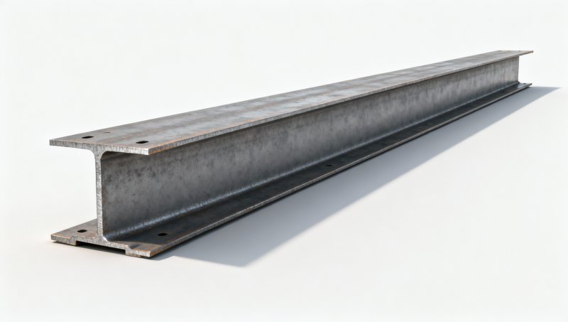
The depth, flange width, flange thickness and web thickness of an I- or H-section affect its behavior in different ways. Overall depth often has a strong influence on bending stiffness about the major axis because it separates the flanges. The flanges contribute substantially to bending resistance, while the web is particularly relevant to shear resistance and local behavior near supports or concentrated loads.
The properties needed for selection are not limited to the dimensions visible on a drawing. Section tables also provide second moment of area, section modulus, mass per unit length and other properties used in design checks. Compare the properties about the intended bending axis: rotating a section can change its stiffness and capacity considerably.
A deeper beam can be efficient, but depth is not free. It may conflict with ceiling zones, ducts, crane clearances or architectural limits. A wider or heavier section may fit the available depth, yet create connection or handling issues. The practical question is therefore not simply “Which beam spans the distance?” but “Which beam meets the checks within the space and restraint conditions available?”
Separate strength from deflection
Strength checks ask whether the member can resist the design actions with the required safety margins. Depending on the governing standard and structural system, these checks can include bending, shear, combined actions, local buckling and lateral-torsional buckling. Deflection is a serviceability check: it asks whether movement under the relevant service loads remains acceptable for the building and its use.
A beam can pass a strength check and still feel too flexible, damage finishes or cause ponding concerns on a roof. Conversely, a member chosen solely to meet a deflection limit still needs all applicable strength and stability checks. The governing criterion depends on the span, loading, restraint and project-specific acceptance limits.
For a simple illustration, the maximum elastic deflection of a simply supported beam under a uniformly distributed load is 5wL4/(384EI). Here, w is the load per unit length, L is the span, E is the elastic modulus and I is the second moment of area about the bending axis. The equation assumes a prismatic member, ideal simple supports, linear-elastic behavior and a constant distributed load; it does not cover every real beam condition.
The span term is worth noticing. If span increases while load per unit length and section stiffness remain unchanged, deflection rises rapidly. This is why extending a bay can demand a much stiffer section even when the increase in span looks modest on a plan. Units must be consistent throughout the calculation, and the result must be compared with the limit that applies to the load case being assessed.
Do not assume that a higher-strength steel grade automatically solves excessive deflection. Higher yield strength can improve resistance in an appropriate design, but elastic stiffness is governed primarily by E and section geometry. Where deflection controls, increasing the second moment of area, changing the support arrangement or reducing the load may be more effective than changing grade alone.
Choose a deflection limit that matches the use
Deflection limits are often expressed as a fraction of span, but the appropriate fraction is not universal. The applicable building code, design standard, project specification and supported materials determine what needs to be checked. A beam supporting brittle finishes or sensitive equipment may require a different assessment from one carrying a roof without a finished ceiling.
Clarify whether the limit applies to total deflection, variable-load deflection or movement occurring after finishes are installed. These are not interchangeable. A member may be acceptable under one criterion and fail another because the timing and combination of loads differ.
Camber can help manage the appearance or effect of anticipated dead-load deflection, but it does not make the beam intrinsically stiffer. It also introduces fabrication and erection tolerances that should be considered in the design. Vibration, floor comfort and equipment sensitivity may need separate assessment even where a calculated static deflection meets the specified limit.
Check restraint and connections before settling on a section
The compression flange of a bending member may move laterally and twist if it is not adequately restrained. Lateral-torsional buckling resistance depends on the unbraced length, load position, moment distribution and section properties, among other factors. A floor deck, purlin or brace should only be treated as restraint where its strength, stiffness and connection are adequate for that purpose.
Check both permanent and temporary conditions. A beam that will eventually be restrained by a floor system can be vulnerable during erection, before the deck or bracing is installed. That construction-stage condition may influence the selected member or require a documented temporary restraint plan.
Connection geometry can also decide between otherwise suitable sections. Review bolt access, weld space, end-plate dimensions and the effect of copes or web openings. Near supports and concentrated loads, bearing, web yielding or buckling, and the possible need for stiffeners deserve attention. A lighter section that requires extensive stiffening or difficult fabrication is not necessarily the lower-cost solution.
Compare options using the same design basis
When reviewing alternatives, record the assumptions beside each result. A comparison loses its value if one option uses a shorter unbraced length, a different load combination or composite action that has not been demonstrated for the other. A useful evaluation record includes:
- Span, support model and locations of distributed and concentrated loads.
- Section designation, orientation, material grade and relevant section properties.
- Strength, stability and serviceability checks, including the governing load combinations and limits.
- Restraint assumptions, connection details and any construction-stage conditions.
- Fabrication, coating, transport and installation constraints that affect the complete solution.
This record makes it easier to identify why one section is preferable. For example, a deeper member may reduce deflection without increasing mass as much as a shallower alternative, but only if the available floor depth and lateral restraint permit it. If headroom is fixed, a heavier shallow section or an engineered change to the support layout may be more realistic. Any proposed substitution needs to be checked against the same design criteria and approved through the project’s design process.
Translate the design into a clear supply specification
A section designation alone is not always enough for international purchasing. Confirm the dimensional series, material specification and grade, required lengths, quantity, tolerances and any testing or inspection documentation. ASTM, EN, JIS and GB designations are not automatically interchangeable: nominally similar sections or grades may differ in dimensions, properties, chemistry, tolerances or documentation requirements.
If a supplier proposes an equivalent, compare the actual section properties and material requirements rather than relying on a similar name or weight. The engineer responsible for the design should review the substitution, including its effect on connections and stability. Confirm whether cut lengths, drilled holes, surface preparation and protective coatings are part of the supply scope; these details affect both lead time and site work.
Hongteng Fengda supplies structural steel beams and other profiles for international projects, including standard and customized requirements. Early discussion of the required standard, section series and documentation can help distinguish a design issue from an availability issue before drawings are finalized. For packages that also include separate carbon-steel products, its Wire Rod offering should be specified and verified for its own intended use; it is not a substitute for a structural beam section.
Before releasing an order, reconcile the structural calculations, fabrication drawings and purchase specification. The most useful final check is whether they describe the same beam, grade, restraint assumptions and delivery requirements—not merely whether the nominal depth looks right for the span.
Please give us a message


Please enter what you want to find