Round or slotted holes in steel angles for adjustable connections?
Choosing round or slotted holes in steel angles affects more than installation convenience: it influences adjustment range, load transfer, and connection reliability. For buyers sourcing angulo con perforaciones—steel angles with holes—the decision depends on bolt specifications, slot orientation, edge distances, and applicable design requirements. Round holes generally suit fixed positioning. Slotted holes provide directional adjustment, but the connection must still perform reliably after alignment.
The most useful starting question is not “Which hole is easier to install?” It is “Should this connection stop moving once the bolts are tightened, or must it remain capable of movement?” Those are different engineering requirements. Treating them as interchangeable is where otherwise straightforward angle connections become troublesome.
Separate installation adjustment from movement in service
Consider a steel angle supporting a secondary framing member against an existing column. Small differences in fabrication, surveying, and erection can leave the mating holes slightly misaligned. A slot can accommodate that mismatch without forcing the installer to enlarge holes on site. Once positioned, however, the bracket may need to resist its design loads without appreciable displacement.
A facade support accommodating thermal expansion has a different purpose. Here, movement may be intentional throughout the building’s life. Simply specifying a slot and tightening an ordinary bolt does not create a dependable sliding connection. Clamping friction can prevent movement, while uncontrolled loosening can compromise retention. Such details may require an engineered assembly with controlled clearance, suitable bearing surfaces, and a defined restraint arrangement.
For selection purposes, distinguish three conditions: fixed positioning, adjustment followed by locking, and deliberate movement in service. Standard round holes are a sensible baseline for the first. Slots can suit the second. The third requires a movement detail, not merely a different hole shape.
Round holes are the baseline when adjustment has little value
Round holes normally provide bolt clearance rather than a close-fitting pin connection. Some initial movement is therefore possible before the bolt bears against the hole, depending on the connection arrangement. Nevertheless, their geometry makes positioning and inspection relatively straightforward, and avoids the additional directional considerations introduced by slots.
They are usually preferable where mating components are produced from coordinated drawings, erection tolerances are manageable, and the connection does not need a deliberate adjustment range. Examples include repeatable shop-fabricated assemblies and brackets located using a reliable drilling template.
Round holes also remove one procurement ambiguity: installers cannot reverse the intended adjustment direction. That matters when many similar angles arrive at a site. If only a few locations need adjustment, making every bracket slotted can introduce unnecessary detailing and inspection work. A separate adjustable part number may be the cleaner solution.
Slot orientation determines both usefulness and risk
A slot adjusts mainly along its long axis. A vertical slot helps with elevation differences; a horizontal slot helps with lateral positioning. Neither solves every alignment problem, and neither corrects an angle whose leg is twisted or whose supporting surface is substantially out of plane.
The same orientation also changes how the bolt can engage the hole under load. When force acts along the slot, the bolt may travel toward a rounded end before bearing develops. When force acts across it, engagement occurs against a side of the slot. That geometric distinction does not establish a permissible capacity by itself: the governing design rules may restrict hole types, require particular connection categories, or modify resistance calculations.
A practical example is an elevation-adjustable angle carrying downward load. A vertical slot provides the desired installation adjustment, but its long axis also follows the load direction. If displacement would damage supported finishes or alter alignment, the designer must address slip explicitly rather than assume tightening eliminates the issue.
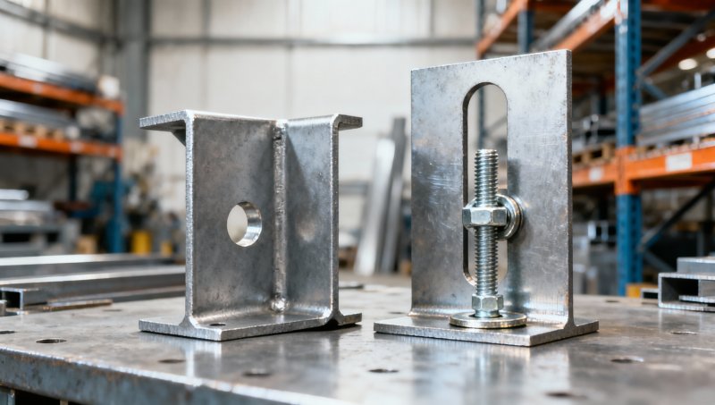
An approval drawing should show the slot axis, anticipated load directions, bolt positions, and angle edges together. An isolated note reading “slotted holes” leaves too much to interpretation.
Usable adjustment is not the overall slot length
For a bolt passing through an unobstructed slot, the approximate geometric travel of its center along the slot is the overall slot length minus the bolt shank diameter. This is only a geometry check, not a recommended slot size or a structural acceptance criterion.
Actual usable adjustment can be smaller because of washer coverage, mating-hole position, tool access, adjacent components, or restrictions on the final bolt location. A nominally centered bolt offers travel in both directions; a bolt initially near one end does not. Specify the required adjustment from a defined datum, including whether it is one-sided or available on either side of nominal position.
Check the complete load path, not just the hole
In a bearing-type connection, bolt shear and contact between the bolt and connected material contribute to load transfer after available clearance is taken up. In a slip-critical connection, resistance to slip depends on a qualified assembly, including bolt pretension and specified faying-surface conditions. A slot is not automatically unacceptable, but its use must satisfy the applicable rules.
“Use high-strength bolts” is therefore an incomplete instruction. Bolt grade, installation method, surface preparation, hole category, and inspection requirements must work together. Paint or galvanizing on the faying surfaces cannot simply be assumed to provide the required slip resistance.
Steel angles introduce another complication: loading one leg can create eccentricity and local bending. The outstanding leg may deform, and some arrangements develop prying effects. A satisfactory bolt calculation does not establish that the angle itself is adequate.
- Check bearing, tear-out, net-section rupture, and block shear for the actual hole geometry and load direction.
- Verify leg thickness, local bending, and the eccentricity between the applied load and supporting connection.
- Check edge distances and bolt spacing using the governing standard’s definitions for the selected hole type.
- Assess serviceability where small displacement could damage finishes, disturb equipment alignment, or redistribute load.
The remaining material between a slot end and a free edge deserves particular attention. A dimension to the slot center alone can conceal a small ligament. Drawings should identify overall slot dimensions and location clearly enough for both structural verification and shop inspection.
Detail washers, access, and finishing before production
Do not assume a standard washer adequately covers every slot. Depending on the hole type, bolt assembly, and governing specification, a plate washer or another prescribed arrangement may be necessary. Coverage should be checked at the permitted extreme bolt positions, not only with the bolt centered.
On narrow angle legs, the washer or bolt head can clash with the root radius. A wrench may also fit during a trial assembly but become inaccessible once the angle is installed beside a beam flange or concrete face. These are good reasons to review a section through the complete connection rather than approve a flat hole-pattern drawing alone.
Hole production and finishing also need agreement. Punching, drilling, and thermal cutting can produce different edge conditions and are subject to project requirements. Burrs, distortion, or coating buildup can obstruct the intended fit. If adjustment is central to the design, inspect finished components rather than relying solely on pre-coating dimensions.
Field enlargement should not become the default solution for poor fit-up. It can change hole classification, reduce edge distances, and damage protective coatings. Any proposed modification needs the responsible engineer’s approval and an appropriate repair procedure.
What to put in the inquiry and approval drawing
For customized perforated angles, the purchase description should separate material compliance from connection geometry. An angle supplied to a material standard is not automatically an approved bolted connection. North American projects may reference AISC and RCSC requirements, while European projects may use EN 1993-1-8 and EN 1090-2. The applicable editions and project requirements should be stated, not inferred from the destination country.
A useful inquiry includes:
- Angle dimensions, thickness, length, steel grade, and whether the section is hot-rolled or cold-formed.
- Bolt specification, hole classification, and round-hole diameter or slot width and overall length.
- Hole coordinates, slot orientation, reference datums, and required finished dimensional tolerances.
- Coating requirements, washer details, and any restrictions on hole-making methods.
- The approved drawing revision, inspection scope, material documentation, and part-identification requirements.
Hongteng Fengda manufactures and exports angle steel, channels, beams, cold-formed profiles, and customized structural components from China. For an adjustable angle inquiry, providing the mating-part detail alongside the angle drawing helps the manufacturer review fabrication feasibility, hole access, and inspection needs. It does not replace the project engineer’s connection design.
Where the angle connects to reinforced concrete, keep reinforcement procurement separate from the bracket specification. HRB400 Rebar, with a specified minimum yield strength of 400 MPa, may form part of the concrete reinforcement package; it is neither the angle’s material grade nor evidence of anchorage capacity. Anchor position, embedment, concrete edge distance, and reinforcement congestion still require coordinated review.
The decision should end with a specific requirement: use round holes where fixed geometry is practical; use slots where a defined adjustment range is genuinely needed and the resulting connection has been checked. If movement must continue in service, specify an engineered movement detail. Before releasing production, ask for one drawing showing the bolt at both adjustment limits, with washers, angle edges, and mating components visible. That review can expose a problem that a hole-size schedule alone will miss.
Please give us a message


Please enter what you want to find