Choose an L bar with holes by matching the complete hole pattern to the existing assembly: bolt centers, hole diameter, row position, and the distance from the end to the first hole. Matching the angle’s leg sizes alone does not establish fit. A replacement can have the correct overall dimensions and still leave the last bolt out of alignment.
A standard perforated angle is suitable when its drawing matches these measurements and its section meets the application’s load requirements. If the existing pattern is irregular, the bolts are fixed in position, or the connection allows little adjustment, a custom-drilled angle is often the more practical choice. Start by recording the assembly as it sits, then compare that record with a dimensioned supplier drawing.
Measure the whole bolt pattern before choosing the angle
Support and secure the assembly before loosening any connection. Where removal is practical, an undamaged original bracket can help establish the pattern. However, worn holes, bent legs, and previous modifications can make an old part a poor reference. Measure the mating component or fixed bolts as well, especially when the replacement must fit an existing frame.
Bolt spacing means center-to-center distance. Measuring the empty gap between two bolts gives a different dimension. For equal-diameter round holes, measuring between corresponding edges can help establish center spacing. With unequal, elongated, or damaged holes, that shortcut becomes unreliable; locate the centers independently.
Record every hole from one common reference point, such as the left end of the angle. This reference is called a datum. Dimensions taken from a shared datum describe where each hole belongs without allowing small errors between successive measurements to accumulate.
Also measure the overall distance between the first and last centers. Checking only the first pair can miss a repeating pitch difference that becomes significant farther along the angle. An apparently regular pattern may also include a different spacing near an end, splice, or attachment.
- Longitudinal position: each hole center measured from the same end.
- Row position: the distance from each center to a clearly identified leg edge or reference face.
- Hole size and shape: round diameter, or slot width, length, and direction.
- Section dimensions: both leg widths, steel thickness, and overall length.
- Installation orientation: which leg attaches to the frame and which way the other leg projects.
For fixed studs or anchors, record their actual positions rather than assuming they follow an old drawing perfectly. Note whether the studs are parallel and whether the mounting surface is flat. A pattern can match on paper while tilted studs or a distorted base prevent the angle from seating.
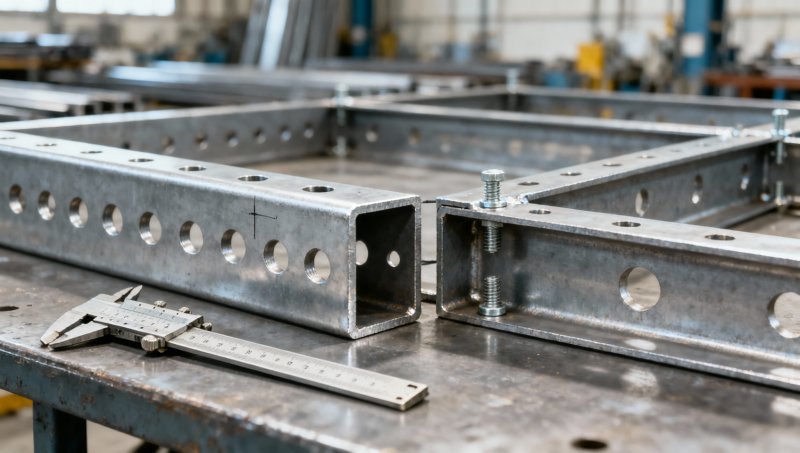
Check which leg is drilled—and where the row sits
Supplier descriptions such as “perforated angle” or “drilled L section” can refer to holes in one leg, both legs, or staggered rows. Product photographs rarely provide enough detail to distinguish these arrangements. Request a drawing that shows the section and the hole layout together.
With unequal-leg angle, identify the wider and narrower legs explicitly. Turning the angle around may change the position of the projecting leg, interfere with nearby equipment, or move the load away from its intended support point. A pattern that fits after rotation is useful only if the installed orientation also works.
The transverse location of the hole row matters as much as bolt pitch. A row positioned too close to the internal corner can leave inadequate room for a washer, bolt head, or socket. Rolled angles have an internal root radius; formed angles have a bend radius. Neither corner should be treated as a perfectly sharp intersection.
Check that washers can sit flat and that the required tools can reach the fasteners. If both legs contain holes, inspect access with the mating components in place. A bolt may pass through its hole but still be impossible to tighten because the adjacent leg blocks the wrench.
Keep edge distance distinct from row position. Edge distance is measured from the hole center to the relevant free edge or end. The amount needed depends on the hole, material, fastener, and connection design. A hole being physically inside the leg does not establish that enough steel remains around it to carry the load.
Separate bolt clearance from permission to change the connection
A clearance hole is larger than the bolt shank so the bolt can pass through during assembly. That clearance accommodates limited variation, but it should not be treated as a general allowance for an incorrect pattern.
The available movement depends on the entire connection. An angle sliding over fixed studs has different fitting constraints from two loose plates joined by removable bolts. Several bolts must fit simultaneously, and the angle’s position may also be controlled by a shoulder, adjacent bracket, or equipment surface.
Ask the supplier for hole-position tolerances as well as hole-size tolerances. “Standard tolerance” is not enough to assess a close-fitting replacement. For longer patterns, dimensions locating the first and last holes help reveal whether the supplied part will remain aligned across its full length.
Evaluate the least favorable combination: the smallest permitted finished hole, the largest relevant bolt diameter, and the allowed positional variation. Include coating buildup where it affects clearance. If fit depends on every dimension falling at the favorable end of its tolerance, the specification needs adjustment before ordering.
Do not assume that larger holes solve the problem without consequences. Enlarging them removes steel and can affect bearing, movement, and washer coverage. Slots provide adjustment in a defined direction, but their suitability depends on how the connection transfers load. A connection designed to resist slipping may require specific hole geometry, washers, and installation procedures.
Choose between stock perforations, slots, and custom drilling
The useful distinction is how well each option fits the existing assembly while preserving the required connection behavior.
Stock perforated angle can be convenient for light frames and adjustable supports when the existing pattern genuinely matches. Check what happens when it is cut to length: the cut may pass through a hole or leave insufficient material between the final hole and the end.
Slots are useful when adjustment serves a purpose, such as positioning a component before tightening. They are less suitable when the assembly needs repeatable, positive location and movement would be unacceptable. Slot direction also matters; a slot running along the angle cannot correct an error across the leg.
Custom drilling is a sensible choice when adapting stock material would involve repeated enlargement, unused holes, or extensive fitting. It also allows the required holes to be placed without introducing unnecessary perforations elsewhere. For a repeated order, an approved sample or checking fixture can help establish fit before full production.
A matching hole pattern still needs the right steel section
Once the geometry fits, check whether the angle can perform its job. A light formed bracket and a structural angle may share similar outside dimensions while differing substantially in thickness, corner geometry, and stiffness. Product names alone do not establish interchangeability.
Match the specified steel grade and section requirements for the existing application. Increasing thickness may improve stiffness, but it also changes the fastener grip length, available thread engagement, and clearance around adjacent parts. Reducing thickness to make installation easier can weaken the support or change how it deflects.
The load direction matters. An angle carrying weight on its projecting leg may bend or twist differently from one used mainly to locate a panel. Holes reduce the remaining cross-section, and closely spaced holes or holes near an edge can affect the connection’s capacity. For a load-bearing replacement, fit should be assessed alongside the approved connection design.
Finish deserves a separate check. Zinc coatings, paint, and other protective systems need to suit the exposure and the fabrication sequence. Drilling or cutting a finished angle exposes fresh steel; deburring and appropriate coating repair should be included in the work plan. Sharp burrs can also prevent flat seating and interfere with bolt insertion.
For a bracket carrying Electrical Conduit Galvanized, check the conduit clamp’s hole spacing and clearance as well as the angle’s frame connection. Galvanizing helps protect the conduit from corrosion, while the supporting angle needs its own suitable finish. The conduit’s dimensions do not establish the bracket’s required steel thickness or bolt pattern.
Give the supplier a drawing that describes installation fit
A request for “the same L bar with holes” leaves too much open to interpretation. Photographs show context, but a dimensioned sketch communicates the features that determine whether the part will install.
Your drawing should identify the measurement units, reference end, drilled leg, orientation, all hole centers, hole sizes, section dimensions, length, material requirement, and finish. Show slots with both dimensions and their direction. Distinguish dimensions taken from the existing assembly from dimensions required for the replacement.
Identify the features that must fit fixed components. If the angle must clear a nearby housing or allow a socket to reach a bolt, show that restriction. This gives the manufacturer a reason to control the relevant dimensions rather than focusing only on nominal angle size.
Hongteng Fengda supplies standard angle steel and customized structural steel components. When requesting a replacement, provide the installation drawing so the quotation can address the drilling pattern, material, finish, and inspection requirements together. A list of general standards does not replace a defined grade and an agreed fabrication drawing.
Trial-fit before final tightening
Check the delivered part’s orientation and critical dimensions before installation. With the assembly supported, place the angle against its mounting surface and insert all fasteners loosely before tightening any one of them fully. This reveals whether the complete pattern fits without pulling the part out of position.
If the first bolts enter but later ones do not, examine accumulated spacing differences and the reference-end offset. If the centers align but the angle will not sit flat, inspect burrs, corner interference, distorted steel, and obstructions behind the leg.
Do not use bolt tightening to draw a mismatched angle into place. Resolve the cause of resistance before completing the connection, then follow the specified fastening procedure. The replacement is ready when all intended fasteners fit, the angle seats properly, tool access is available, and the section and finish satisfy the application requirements.
Please give us a message


Please enter what you want to find