For tight bends and repeatable wire forms, start with a low-carbon steel wire supplied in a suitable annealed or controlled-drawn condition, then verify its performance on the actual tooling. A low carbon designation alone does not guarantee that the wire will bend without cracking or return consistently to the required dimensions.
On a forming line, one coil may feed smoothly while another produces springback, tool marks, or fractures at the same bend. The useful comparison is therefore not tensile strength in isolation, but the combination of chemistry, processing condition, diameter, surface quality, and demonstrated forming behavior. When evaluating alambre bajo carbono, define the finished shape and process before requesting material quotes.
Begin with the severity of the intended form
A shallow bend in a large wire loop places different demands on the material than a tight hook, a closed eye, or several bends made in quick succession. Identify the smallest inside bend radius, wire diameter, bend angle, and any straightening or flattening operations before comparing grades. Also note whether the part must hold a close profile after forming or tolerate further adjustment during assembly.
The ratio of inside bend radius to wire diameter is a useful way to describe bend severity. A smaller ratio generally means greater strain on the outside of the bend. It is not, by itself, a universal pass-or-fail limit: wire condition, surface defects, tooling, and the test method all affect the outcome. Put the actual radius and diameter on the drawing rather than asking for “good bendability.”
For a simple bracket or tie with generous bends, a moderately drawn wire may provide adequate formability and useful stiffness. A compact form with tight radii may need a softer condition, subject to confirmation that the finished part still has enough strength and dimensional stability. Where a part must act as a spring, ordinary low-carbon wire selected only for ease of bending may not provide the required elastic performance.
Compare material condition, not just carbon content
Low-carbon steel generally offers better formability than higher-carbon steel, but the carbon level is only one part of the specification. Composition ranges, drawing reduction, heat treatment, and subsequent handling all affect the properties presented to the forming machine. Two wires described as low carbon can behave differently if one has been heavily cold drawn and the other has been annealed.
Annealed wire
Annealing is commonly used to restore ductility after drawing. Soft annealed wire is often a starting point for tight bends, twisting, or repeated deformation. It can reduce the forming force required, but excessive softness may make feeding, straightening, or maintaining the final shape more difficult. The degree of softness should therefore be agreed against the part and process rather than assumed from the word “annealed.”
Cold-drawn wire
Cold drawing increases strength and hardness through work hardening, while generally reducing the available ductility. A controlled-drawn condition can be appropriate when the form is relatively open or when the part needs more stiffness. However, a wire that meets a tensile-strength target may still be unsuitable for a sharp bend. Request the processing condition alongside the mechanical-property range and confirm it with a representative forming trial.
Specify the applicable material standard and grade by agreement with the supplier, including the edition and any supplementary requirements relevant to the purchase. Do not assume that similar grade names across different standards prescribe identical chemistry, tolerances, or delivery conditions. The ordered specification and the inspection document should identify the same material and condition.
Read mechanical properties in the context of the process
Tensile strength helps compare resistance to pulling, but it does not fully describe how a wire behaves around a small forming pin. Yield behavior influences permanent deformation and springback; ductility indicates the material’s capacity to deform before fracture. Elongation can help compare ductility when measured under comparable test conditions, although it should not replace a bend test for a demanding geometry.
For a production evaluation, agree on property ranges rather than requesting only a maximum tensile strength. A wire that is too strong may crack or require excessive force; one that is too soft may deform during feeding or fail to retain the intended shape. Ask whether reported values apply to the finished wire as supplied and whether they represent each production lot or another agreed sampling basis.
Springback deserves separate attention. After the tooling releases the wire, elastic recovery changes the angle or radius. Strength and stiffness influence this response, but so do wire diameter, bend geometry, and tooling. A forming program can compensate for predictable springback; it is harder to control when properties vary substantially between coils. Compare the spread of results across representative samples, not just the average angle from one successful part.
Diameter and surface condition can determine the outcome
Diameter affects both bend strain and the force needed to form the wire. A small change in diameter can alter how the wire sits in a groove, feeds through guides, and contacts a forming pin. Check the specified diameter tolerance against the machine setup and the finished-part tolerance. Measure at several points along a sample and in more than one orientation where practical, especially if out-of-roundness could affect feeding.
Inspect the surface before attributing every fracture to chemistry. Seams, scratches, pits, corrosion, and die marks can act as local stress concentrations on the outside of a bend. A mark that appears harmless on straight wire may open when stretched around a small radius. Check whether the defect was present on the incoming wire or introduced by straighteners, guides, clamps, or worn tooling.
Surface finish also affects friction and cleanliness. Lubricant or drawing residue may improve processing in one operation but interfere with welding, coating, or assembly later. State whether the wire must be clean, oiled, coated, or suitable for a subsequent finish. Agree on an acceptable surface condition and inspection method; “bright” or “smooth” alone may leave too much room for interpretation.
Coated wire requires an additional check. Forming can damage a coating at the bend, particularly when the radius is tight or the tooling grips aggressively. If corrosion protection is required, determine whether coating before or after forming is practical, and assess coating integrity on the finished geometry. The steel’s bendability and the coating’s ability to remain intact are separate acceptance questions.
Use a trial that resembles the real operation
A generic material certificate is useful for screening, but a representative trial is the stronger basis for deciding between otherwise acceptable wires. Run samples through the intended straightening and forming sequence, including the smallest radius and any secondary operation that strains the same area again. Record the wire condition and coil identification so the result can be traced back to the supplied material.
- Set a baseline. Document wire diameter, tooling dimensions, machine settings, bend sequence, and the finished-part dimensions to be checked.
- Form representative pieces. Include the most severe bend and the normal production feed direction. Avoid judging material from a single manually bent sample when the final process is automated.
- Inspect the outside of the bend. Look for visible cracking, opened seams, coating damage, and tool impressions. Agree in advance on any magnification or additional inspection needed for the part.
- Measure the released form. Check the angle, radius, overall profile, and any dimensions affected by springback after the part is removed from the tooling.
- Repeat across representative material. Where practical, sample more than one position in a coil and more than one coil or lot. This helps distinguish a stable material response from a single favorable result.
Set acceptance criteria before the trial. A critical formed component may need a defined inspection method and documented limits; a noncritical tie may be judged by simpler visual and dimensional checks. In either case, a pass on one bend should not be taken as proof that the wire will perform in every geometry or production setup.
When a bend fails, separate material effects from machine effects
A fracture confined to one tooling station does not automatically justify changing grade. Equally, repeated cracking across sound tooling should not be masked by reducing production speed alone. Preserve failed samples and identify the bend location, coil, and machine settings so that incoming-material and process variables can be compared.
Keep solid forming wire separate from wire rope
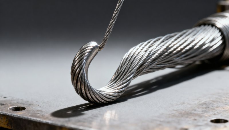
Product form matters as much as the word “wire.” Solid low-carbon wire is selected here as feedstock for discrete bent parts. Galvanized Steel Wire Rope is a stranded assembly intended for different duties, including crane, elevator, and other cable applications. Its listed constructions, such as 6X19+FC and 6X19+IWR, describe arrangements of wires, strands, and cores—not interchangeable grades of solid forming wire.
The rope information lists diameters from 1.0 to 22 mm and normal tensile strengths from 1470 to 1960 MPa. Those figures should not be used as selection targets for a low-carbon wire-forming application. Where a design genuinely calls for a flexible cable rather than a permanently bent solid form, evaluate rope construction, diameter, finish, and the requirements of the intended service separately.
Turn the evaluation into an order specification
Once a candidate has passed the forming trial, record the agreed material grade and standard, delivery condition, diameter and tolerance, surface or coating requirements, and mechanical-property limits. Include packaging and coil requirements where they affect feed direction, handling, or identification. Reference the part drawing and any representative bend-test geometry rather than relying on a broad request for “soft wire.”
Also agree on lot identification, inspection documents, sampling, and the procedure for reporting material that falls outside the specification. If a process change, substitute grade, or different heat-treatment condition is proposed later, compare it with the approved condition and repeat the relevant forming checks before releasing it to production. This preserves the connection between the wire that was qualified and the wire actually delivered.
Please give us a message


Please enter what you want to find