Accurately calculating the load capacity of an H-beam in multi-story buildings requires more than just plugging numbers into a standard formula. The core judgment lies in balancing the applied moments, shear forces, and axial loads against the beam's section modulus, yield strength, and unbraced length. For technical evaluators, the immediate priority is to ensure that the selected steel grade and cross-sectional dimensions can withstand both gravity and lateral loads without exceeding allowable stress or deflection limits, while accounting for lateral-torsional buckling in unbraced segments.
When designing for multi-story structures, the complexity increases due to cumulative loading and dynamic forces. The calculation process must systematically address load combinations, material behavior under stress, and stability criteria. This guide outlines the practical methodology for evaluating H-beam load capacity, highlighting the critical parameters that influence structural integrity and the material considerations necessary for reliable performance in demanding environments.
Defining the Load Combinations
Before selecting a specific beam size, the exact nature of the loads must be quantified. In multi-story buildings, these beams typically serve as primary girders or secondary beams supporting floor slabs. The total load is not merely the sum of the building's weight. Evaluators must calculate dead loads, which include the weight of the structure itself, floors, walls, and fixed equipment, alongside live loads representing occupants, furniture, and movable partitions.
In high-rise or multi-story contexts, environmental loads become equally critical. Wind loads exert lateral pressure on the building envelope, transferring forces to the horizontal framing system. Seismic loads introduce dynamic, cyclical stresses that require the steel to possess adequate ductility. Building codes dictate specific load combination factors. For instance, a typical strength design combination might be 1.2 Dead + 1.6 Live + 0.5 Wind. Failing to apply the correct load factors will result in an under-designed beam, compromising the entire structural frame.
Evaluating Section Properties and Material Yield
Once the factored loads are established, the next step is determining the required section modulus and moment of inertia. The maximum bending moment dictates the required elastic section modulus. By dividing the maximum moment by the allowable bending stress of the steel, evaluators can identify the minimum geometric properties the beam must possess.
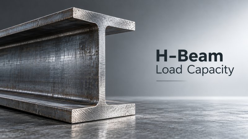
The material yield strength is the baseline for these calculations. Standard structural carbon steels offer yield strengths ranging from 345 MPa to 355 MPa. However, the actual stress distribution within the beam is not uniform. The flanges resist the majority of the bending moment, while the web primarily handles shear forces. Therefore, optimizing the flange width and thickness relative to the web depth is crucial. A deeper beam generally provides a higher moment of inertia, reducing deflection, but it may be more susceptible to local buckling if the web is too thin. Evaluators must verify the width-to-thickness ratios of the flanges and web to ensure the section is classified as compact, allowing it to reach its full plastic moment capacity before local buckling occurs.
Checking Stability and Deflection Limits
Bending strength is only one part of the equation. In multi-story buildings, beams are often part of a continuous frame, and their unbraced length significantly impacts their load capacity. Lateral-torsional buckling is a primary failure mode for beams subjected to bending about their strong axis. If the compression flange is not adequately braced, it can buckle sideways and twist the entire section.
Calculating the critical buckling moment requires analyzing the unbraced length of the beam, the torsional constant of the cross-section, and the modulus of elasticity. For long spans without intermediate bracing, the nominal moment capacity must be reduced. Evaluators often address this by specifying lateral bracing at regular intervals or selecting beams with heavier flanges.
In continuous beams spanning over multiple supports, the moment of inertia and the distribution of bending moments change significantly compared to simply supported beams. Evaluators must calculate the effective moment of inertia, considering the cracking of concrete in composite sections or the partial yielding in steel sections, to accurately predict deflections. Furthermore, the lateral-torsional buckling modification factor accounts for the shape of the bending moment diagram between braced points. Applying the correct modification factor prevents overly conservative designs and allows for more efficient material utilization.
Material Selection for Connections and Auxiliary Components
While the primary load-bearing beams are typically manufactured from high-strength carbon steel, the surrounding environment and specific structural nodes often demand different material properties. In multi-story buildings, especially those located in coastal areas, industrial zones, or facilities with high humidity, the connection plates, gussets, and auxiliary brackets are highly vulnerable to corrosion.
When standard carbon steel connections are insufficient for the environmental exposure, engineers may specify corrosion-resistant materials for these critical nodes. For instance, a 430 Stainless Steel Plate is frequently utilized for connection brackets, architectural trim, and non-structural auxiliary components in such demanding conditions. This specific grade combines good corrosion resistance with useful mechanical properties, making it highly suitable for applications where resistance to nitric acid attack or general atmospheric corrosion is required.
Integrating stainless steel components into a carbon steel framing system requires careful evaluation of galvanic corrosion. When dissimilar metals are in direct contact in the presence of an electrolyte, the less noble metal will corrode faster. Evaluators must ensure that proper isolation methods, such as non-conductive pads or specialized coatings, are specified between the carbon steel beam and the stainless steel connection plates. Furthermore, the thermal expansion coefficients of the different materials must be accounted for in the connection design to prevent stress buildup during temperature fluctuations. Utilizing materials like the aforementioned 430 Stainless Steel Plate for specific high-risk zones ensures long-term durability without over-engineering the entire primary frame with expensive alloys.
Common Calculation Pitfalls in High-Rise Design
Technical evaluators frequently encounter specific pitfalls when calculating load capacities for multi-story structures. One common error is assuming that the full plastic moment capacity can be utilized for all beams. In reality, many beams in a multi-story frame are subjected to combined bending and axial forces, especially when they act as part of a moment-resisting frame or support heavy gravity columns. The interaction between axial compression and bending moment reduces the available plastic capacity. Evaluators must use interaction equations provided by the relevant design codes to verify that the combined stress ratio remains below the allowable limit.
Another frequent oversight is neglecting the effects of composite action. In modern multi-story buildings, steel beams are often cast integrally with concrete floor slabs using shear studs. This composite action significantly increases the effective moment of inertia and the load-carrying capacity of the beam. If the calculation treats the steel beam and the concrete slab as acting independently, the resulting design will be overly conservative, leading to the selection of unnecessarily heavy sections. Conversely, if the degree of shear connection is not properly accounted for, the calculated capacity may be dangerously optimistic.
Fire resistance is another critical factor that influences the load capacity calculations. Steel loses strength and stiffness rapidly at elevated temperatures. While the primary structural analysis is usually performed for ambient conditions, the design must ensure that the beams can maintain their load-bearing capacity for a specified duration during a fire event. Evaluators often address this by applying fireproofing materials, which increase the cross-sectional dimensions and affect the overall weight and connection details. Alternatively, some advanced calculation methods incorporate the temperature-dependent reduction factors for yield strength and modulus of elasticity to determine the required thickness of the fire protection system.
Finalizing the Selection and Procurement Specs
Once the structural calculations are complete and the optimal beam sizes are determined, the final step is translating these technical requirements into precise procurement specifications. The selection process must account for not only the geometric dimensions and steel grade but also the manufacturing tolerances, surface preparation, and delivery conditions.
For global construction projects, ensuring that the supplied beams comply with international standards such as ASTM, EN, JIS, or GB is non-negotiable. The procurement specifications should clearly define the required test certificates, including chemical composition and mechanical properties like yield strength, tensile strength, and elongation. Additionally, specifying the required surface finish, such as shot blasting to a specific grade and the application of a primer, is crucial for ensuring that the steel arrives on-site ready for fabrication and erection without delays. Evaluators should also consider the constructability of the selected sections, balancing structural efficiency with the logistical constraints of a congested multi-story construction site to ensure the design is practically executable.
Please give us a message


Please enter what you want to find